


- 31 -
Service Manual
In
“FINE
ADJUSTMENT
MODE”
options,
press
“MUTE” key on remote to switch between “cursor”
mode and “data” mode.
•
Cursor mode (cursor flashing): Allows cursor
movement by pressing VOL right - left and CH up
- down.
•
Data mode (cursor fixed): Allows making
adjustment by pressing VOL right - left and CH
up - down.
Procedure:
1.
Enter to “G-EASY” mode (for green):
•
DAC EASY
•
Press POWER on remote
•
TV/VIDEO (repeatedly)
•
R-TUNE (repeatedly)
2.
Press “2” repeatedly and apply the pattern of
crosshatch.
3.
Press “1 or 3” repeatedly until the pattern becomes
green.
4.
Press RECALL to display values.
5.
In “EASY” mode, the adjustment value changes by
4 steps
6.
EASY mode allows to move lines horizontally and
vertically from the center of cursor.
7.
This mode afects a wide area around the cursor
than other adjustment modes, See values on
screen by pressing RECALL on remote (see
figure 53)
8.
Begin adjustment from the center to the edge of
the screen.
9.
Adjust by pressing CH up/down and VOL right/left
on the remote control when the cursor is not
flashing, if the cursor is flashing press MUTE on
the remote.
10. To move the cursor press MUTE on the remote
(cursor flashes), then move the cursor to any of the
9 positions for “EASY” mode(see figure 52)
11. This adjustment may help to make rounded lines
become straight lines
12. Adjust to make lines as straight as possible
13. Enter to POINT “G-POINT” (for green) mode by
pressing TV/VIDEO.
14. “POINT” mode allows to move line horizontally and
vertically from the perimeter of cursor making
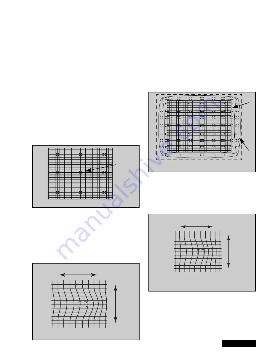
rounded lines become straight (see figure 54)
15. In “POINT” mode, the adjustment data changes by
2 steps, See values on screen by pressing
RECALL on remote.
16. When the cursor is located in the outer area of the
border the cursor starts to flash from one side to
other and the adjustment is for the non-visible area
(inside the ovals area, see figure 54); This applies
to “LINE”, “POINT” & “ORIGIN. POINT” modes.
17. Begin adjustment from the center to the edge of
the screen.
18. Adjust to make lines as much straight as possible
19. When slightly adjustment is needed, use “ORIG.
POINT” mode.
20. To enter to “G-ORIG. POINT” (for green) mode
press TV/VIDEO.
21. With “ORIG. POINT”, the adjustment data changes
by 1 step, this allows more detail in the adjustment.
Display values on screen by pressing RECALL on
remote
Figure 52. EASY adjustment cursor positions
cursor
Figure 53. EASY adjustment
left/right
up/down
Figure 54. POINT & ORIG. POINT cursor positions
Cursor
Flashess
Screen
Frame
Figure 55. POINT & ORIG. POINT adjustment
left/right
up/down
Summary of Contents for PT-51HX42CF
Page 37: ... 37 K Board layout K Board schematic K Board ...
Page 38: ... 38 G Board layout G Board schematic G Board ...
Page 39: ... 39 NOTES ...
Page 40: ...Printed in USA K02042127PL0508 ...
Page 105: ... 65 Notes PARTS LIST ...
Page 106: ... 66 D Board Schematic ...
Page 107: ... 67 D Board Schematic ...
Page 108: ... 68 D Board Schematic ...
Page 109: ... 69 Jumper between pin 7 and pin 1 D Board Schematic ...
Page 110: ... 70 D Board Schematic ...
Page 111: ... 71 D Board Schematic ...
Page 113: ... 73 NOTES NOTES ...
Page 114: ... 74 D Board Layout ...
Page 115: ... 75 D Board Layout ...
Page 116: ... 76 A Board Schematic ...
Page 117: ... 77 A Board Schematic ...
Page 118: ... 78 A Board Schematic ...
Page 119: ... 79 A Board Schematic ...
Page 120: ... 80 A Board Schematic ...
Page 121: ... 81 A Board Schematic ...
Page 122: ... 82 A Board Schematic ...
Page 123: ... 83 A Board Schematic ...
Page 124: ... 84 Board section Top A Board Layout Top left portion ...
Page 125: ... 85 Board section Top A Board Layout Top right portion ...
Page 126: ... 86 Board section Top A Board Layout Bottom left portion ...
Page 127: ... 87 Board section Top A Board Layout Bottom right portion ...
Page 128: ... 88 Board section Bottom side A Board Layout Top left portion ...
Page 129: ... 89 Board section Bottom A Board Layout Top right portion ...
Page 130: ... 90 Board section Bottom A Board Layout Bottom left portion ...
Page 131: ... 91 Board section Bottom A Board Layout Bottom right portion ...
Page 132: ... 92 LG Board schematic TNP2AA112 LG Board schematic ...
Page 134: ... 94 LR Board schematic TNP2AA111 LR Board schematic ...
Page 136: ... 96 LB Board schematic TNP2AA110 LB Board schematic ...
Page 138: ... 98 K Board schematic TNP2AA089 K Board layout TNP2AA089 K Board schematic and layout ...
Page 139: ... 99 G Board schematic TNP2AA090 G Board layout TNP2AA090 G Board schematic and layout ...
Page 144: ...Printed in USA K02042127PL0429 ...


