background image

Troubleshooting

18

If you find any problem, please take the following steps to check.

 LED

The POWER LED (Power) is not lit.

  Check if the power cord is disconnected. Please confirm that the power cord is 

securely connected to the power port.

  Is the Switching Hub operated at temperature in the range from 0 to 45

°

C?

  Ensure that the operating temperature is within the specified range.
  The use of this Switching Hub outside the operating ambient temperature 

range causes the protective device to trip, stopping the PoE power supply.

The Port LED is not lit in Status mode.

  Is the cable correctly connected to the target port?

  Is the cable appropriate to use?

  Is the terminal connected to the relevant port conforming with 10BASE-T, 

100BASE-TX, or 1000BASE-T standard?

  Auto-negotiation may have failed.

  Check the port settings of this Switching Hub or the terminal settings.

  Did you select a correct Port LED display mode using the LED DISPLAY 

CHANGE BUTTON?

The Port LED (Right) lights in orange.

  Loop is occurring. By removing the loop, orange LED will be turned off.

LOOP HISTORY LED Blinks in orange. 

  This is to notify that there is a port in which a loop is occurring, or has been 

removed within 3 days.

 Communications are slow.

  Are the communication speed and mode settings correct?

  If the communication mode setting is incorrect, the operation may be being 

performed in the half-duplex mode.

  Please reconfirm autonegotiation setting.

Do not set the connected equipment to forced full-duplex. 

  Is not the utilization ratio of the network to which this Switching Hub is 

connected too high?

  Try separating this Switching Hub from the network.

Summary of Contents for PN25249-ID

Page 1: ...ing Hub Please read the Important Safety Instructions on pages from 3 to 5 Any problems or damage resulting from disassembly of this Switching Hub by customers are not covered by the warranty I0716 10719 Printed in Japan Switch S24GPWR Model No PN25249 TH PN25249 MY PN25249 ID PN25249 SG 2 12 7 Higashi Shimbashi Minato ku Tokyo Japan 105 0021 2019 ...

Page 2: ... Outline 1 1 Features 1 2 Specifications 1 3 Accessories 1 4 Basic operation 2 Part Names and Functions 2 1 LED display change 2 2 PoE power supply function 3 Installation and Configuration 3 1 Mounting to rack 3 2 Configuration of IP address Basic Troubleshooting 3 6 7 7 8 9 9 10 13 15 16 16 16 18 ...

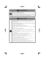
Page 3: ... Do not disassemble and or modify this Switching Hub Deviation could lead to fire electric shock and or equipment failure Do not damage the power cord Do not bend too tightly stretch twist bundle Do not unplug nor plug in the power plug with wet hands Deviation could lead to electrical shock and or equipment failure Do not insert nor drop any foreign objects such as metal or readily combustible th...

Page 4: ... could lead to electric fire shock and or malfunction Unplug the power cord if the STATUS LED blinks in orange system fault Deviation such as keeping connected for a long time could lead to fire Handle the Switching Hub carefully so that fingers or hands may not be damaged by twisted pair port SFP extension slot console port or power cord hook block Do not connect any other devices except for 10BA...

Page 5: ...Communications failures might be generated due to causes such as malfunctions or misoperations while the Switching Hub is being used When using this Switching Hub for applications which require extremely high reliability be careful to expend all possible means to ensure safety and reliability This Switching Hub was not designed nor manufactured with the intention that it be used for applications i...

Page 6: ...igh humidity Possible spilled liquid water Dusty Possible static charge such as carpet Under direct sunlight Possible condensation High low temperature exceeding the specifications environment Strong vibration and or strong shock Please use this Switching Hub in locations where the ambient temperature ranges from 0 to 45 C Failure to meet the above conditions may result in fire electric shock brea...

Page 7: ...Link Aggregation Ports 1 to 22 are set at MDI X default Has the IEEE 802 3az LP1 compliant Energy Efficient Ethernet function hereafter referred to as EEE This function automatically saves power when there is no data communication in the linkup state allowing a reduction in the power consumption of each port Embedded power saving mode detects the connection status automatically and saves power con...

Page 8: ...eues Management method Telnet Console WEB control screen Power supply function Ports 1 to 24 support the IEEE802 3af compatible power supply function Maximum power supply 15 4 W per port 124 W in total Power supply method Altervative A Using idle line 1 2 3 6 Others Port Monitoring PoE Scheduler Power supply AC 100 240V 50 60 Hz 2 6 A Power consumption Normally Max 162 W 24 1 W when not supplying ...

Page 9: ... Then POWER LED Power lights in green STATUS ECO LED Status ECO mode lights in orange and self diagnosis of hardware is executed On completion of self diagnosis POWER LED Power STATUS ECO LED Status ECO mode and the Switching Hub starts operation as a Switching Hub As this Switching Hub succeeds in communicating with a terminal connected to each port LED of the port lights up When the terminal is ...

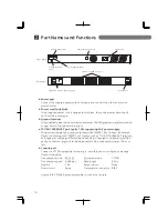
Page 10: ...terminal screw 10 100 1000BASE T port ports 1 24 supporting PoE power supply The port can supply PoE power conforming with IEEE802 3af Connect a Powered Device conforming with IEEE802 3af Devices such as 10 100 1000BASE T terminal hub repeater bridge and Switching Hub can be connected to this port Install the device so that the length of twisted pair cable Cat5e or above becomes 100 m or less Cons...

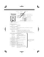
Page 11: ... 124 W Orange Blink A single port s power supply is exceeding the upper limit or the total power supply of the Switching Hub is exceeding 124 W STATUS ECO LED Status ECO mode Green Light Operating in status mode Green Blink Operating in ECO mode All Port LEDs left are turned off Orange Light Starting Orange Blink Malfunction Contact the seller PoE LED Power supply mode Green Light Operating in pow...

Page 12: ...o PoE powered device connected GIGA Green Light Link is established at 1000 Mbps Off Link is established at 100 Mbps or 10 Mbps or no device is connected 100M Green Light Link is established at 100 Mbps Off Link is established at 1000 Mbps or 10 Mbps or no device is connected FULL Green Light Link is established at full duplex Off Link is established at half duplex or no device is connected Orange...

Page 13: ...ting is called as Base mode There are two types of Base modes which are Status mode default setting at shipment and ECO mode To switch the Base mode keep pressing LED DISPLAY CHANGE BUTTON for 3 seconds or more When switching is done successfully 5 LEDs of STATUS ECO LED PoE LED GIGA LED 100M LED and FULL LED are lighted once at the same time they turned off and then it enters a Base mode After sw...

Page 14: ...urring If the loop is still not removed the port will shut down again Remove the loop while the port is shut down During loop is occurring or if loop has occurred within the latest 3 days LOOP HISTORY LED blinks to notify this It is possible to switch loop detection setting OFF ON by using a console cable for detail see the attached CD ROM or by pressing LED DISPLAY CHANGE BUTTON for 10 seconds or...

Page 15: ... LED blinking orange Caution 1 Some PoE powered devices may have a large difference in power consumption between their maximum power use condition and normal condition Carefully configure them so that the upper limit of power supply will not be exceeded 2 If you don t set a priority for power supply or if the same priority is given note that the power supply priority is assigned to the ports in as...

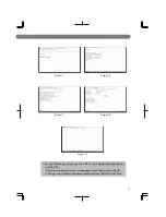
Page 16: ...way Then enter the specified address Screen 4 6 After completing the settings select Q uit to previous menu twice to return to Main Menu Screen 2 Here select Save Configuration to F lash Screen 5 and the command prompt changes to Save current configuration Y N Press Y to save the settings 7 From terminals connected to network confirm that the settings are reflected correctly by executing PING test...

Page 17: ...Screen 3 Screen 5 Screen 4 For the following please see the PDF version Operating Instructions in CD ROM Detailed configuration and management methods using the CLI Configuration and management method from ZEQUO assist Plus ...

Page 18: ...ith 10BASE T 100BASE TX or 1000BASE T standard Auto negotiation may have failed Check the port settings of this Switching Hub or the terminal settings Did you select a correct Port LED display mode using the LED DISPLAY CHANGE BUTTON The Port LED Right lights in orange Loop is occurring By removing the loop orange LED will be turned off LOOP HISTORY LED Blinks in orange This is to notify that ther...

Page 19: ...he cable connected to the port 1 24 that supports PoE power supply Ensure that either the port alone or the entire equipment is not overloaded Is the Powered Device connected to the port compliant with the IEEE802 3af standard or IEEE802 3 at Type 1 15 4W standard Is the STATUS ECO LED blinking orange If you use this Switching Hub outside the operating ambient temperature range high temperature th...

Reviews: