background image

41

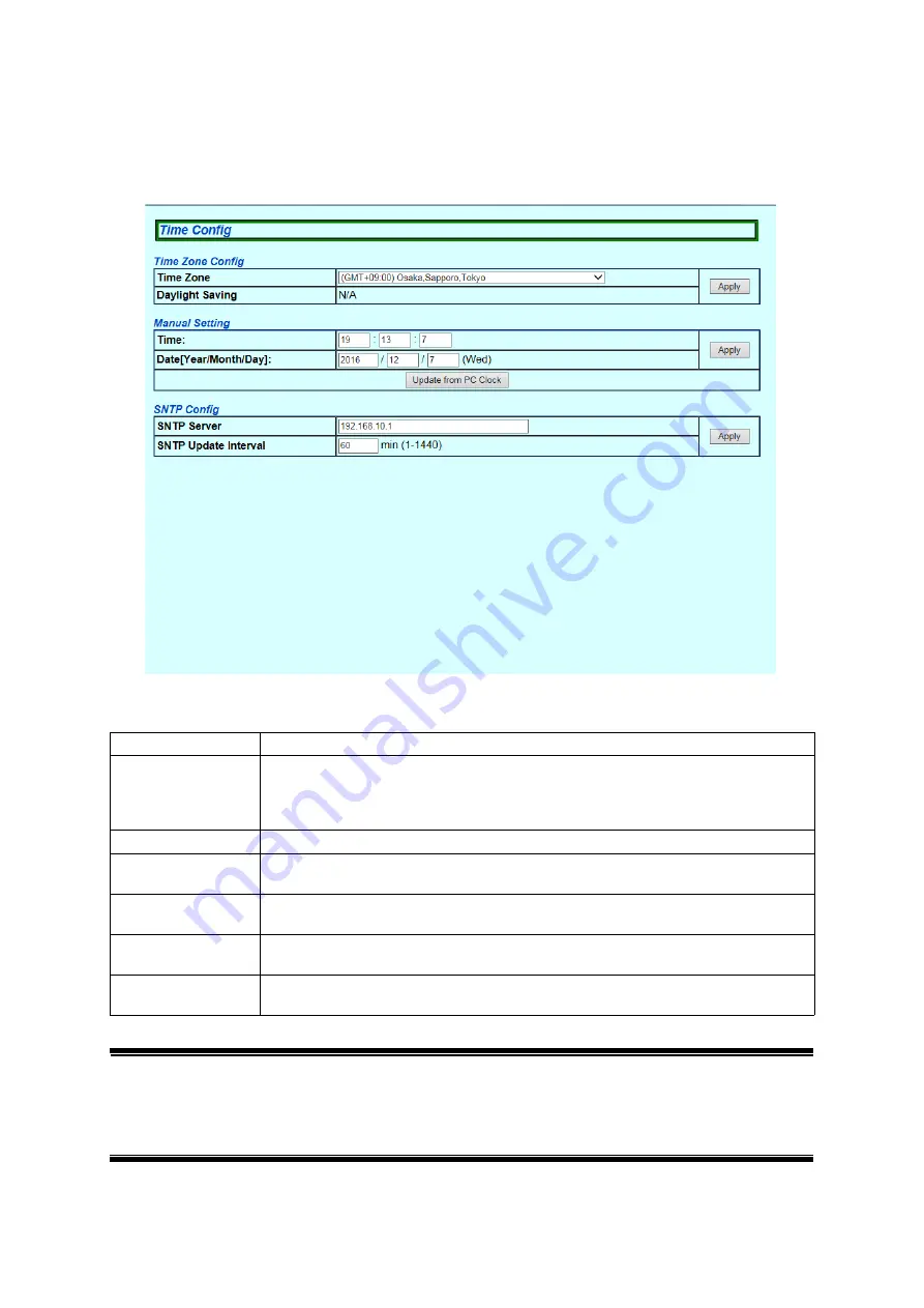
5.1.10. Time Config

Select "Basic Config" and then "Time Config" to open the screen shown in Figure 5-
10
. On this screen, you can configure the SNTP synchronization settings.

Figure 5-10 Time Configuration of This Switch

Screen Description

Note: 

In case the SNTP server is located outside of the firewall, connection with the 
SNTP server may not be possible depending on settings by the network 
administrator. For details, ask your network administrator. 
If you wish to disable the time synchronization function, set the SNTP server 
to "0.0.0.0."

Time Zone

Displays the time zone.

Daylight Saving

Displays the application status of Daylight Saving (Summer time).
In case the set time zone is a zone where Daylight Saving is not applied, "N/A" 
is displayed, and this configuration is not available.
When this switch is used domestically, this configuration is not required.

Time

Displays the time configured manually.

Date (Year/Month/
Day)

Displays the date configured manually.

Update from PC 
Clock

Obtains the date and time from the PC's clock.

SNTP Server

Displays the IPv4 address of the SNTP server that executes time synchroniza

-

tion.

SNTP Update Inter

-

val

Displays the interval time for SNTP synchronization.

Summary of Contents for PN25161

Page 1: ...our product This manual provides important information about safe and proper operations of this Switching Hub Please read Important Safety Instructions on pages 3 to 5 before use For target model names and numbers refer to the next page Under all circumstances customer disassembling of this Switching Hub voids the warranty ...

Page 2: ...above GA AS24TPoE PN25248 TH PN25248 MY PN25248 ID PN25248 SG 1 0 0 07 and above GA AS48TPoE PN25488 TH PN25488 MY PN25488 ID PN25488 SG 1 0 0 10 and above GA AS16T PN25161 TH PN25161 MY PN25161 ID PN25161 SG 1 0 0 07 and above GA AS24T PN25241 TH PN25241 MY PN25241 ID PN25241 SG 1 0 0 07 and above GA AS48T PN25481 TH PN25481 MY PN25481 ID PN25481 SG 1 0 0 10 and above ...

Page 3: ...wer other than AC 100 240 V Deviation could lead to fire electric shock and or equipment failure Do not handle this Switching Hub and connection cables during a thunderstorm Deviation could lead to electric shock Do not disassemble and or modify this Switching Hub Deviation could lead to fire electric shock and or equipment failure Do not damage the power cord Do not bend too tightly stretch twist...

Page 4: ...ould lead to explosion and or fire ヤモヶヵリヰワ Do not connect devices other than 10BASE T 100BASE TX 1000BASE T to a twisted pair port Deviation could lead to equipment failure 4 Use the bundled power cord AC 100 240 V specifications Deviation could lead to electric shock malfunction and or equip ment failure Unplug the power cord in case of equipment failure Leaving failed equipment connected for a l...

Page 5: ...ounting bracket PN71053 wall mount bracket Securely mount and install the Switching Hub so it would not fall under its own weight or the weight of connection cables The Switching Hub may fall causing injury and or equipment failure Perform maintenance at periodic intervals to maintain perfor mance Assign an administrator for this product and make sure to perform periodic maintenance Refer to Panas...

Page 6: ...or devices prone to lightning strikes such as network cameras or wireless access points to a twisted pair port of this Switching Hub overcurrent and or overvoltage caused by light ning passing through the twisted pair cable may affect this Switching Hub causing equipment failure When connecting such devices we strongly rec ommend installing a lightning arrester SPD Surge Protective Device at the t...

Page 7: ...rpet Static electricity could lead to equipment failure Do not apply strong shock including dropping to this Switching Hub Devia tion could lead to equipment failure Please use this Switching Hub in places where the ambient temperature is in the range GA AS16T GA AS24T GA AS48T GA AS16TPoE 80W or less power feed ing GA AS24TPoE 80W or less power feeding 0 50 degrees C GA AS16TPoE GA AS24TPoE GA AS...

Page 8: ...contents described in this document may be changed without prior notice 3 For any questions please contact your dealer Do not cover vent holes of this Switching Hub Covering vent holes could lead to rise of internal temperature and eventual equipment malfunction Do not stack Switching Hubs When placing the Switching Hubs side by side ensure clearance of 20 mm or more When mounting the Switching Hu...

Page 9: ...based Control 25 4 1 Operating Environment 25 4 2 IP Address Configuration 26 4 3 Access to Web Control Function 27 4 4 Displaying Basic Information 29 5 Switch Configuration 31 5 1 Basic Config 31 5 1 1 Administration Config 31 5 1 2 IP Config 32 5 1 3 Basic Port Config 33 5 1 4 Extend Port Config 35 5 1 5 Power Saving Config 36 5 1 6 System Security 37 5 1 7 Syslog Transmission Config 38 5 1 8 I...

Page 10: ...y Info 62 5 2 14 Port Group Config 63 5 3 System Tools 64 5 3 1 Software Update 64 5 3 2 Reboot 65 5 3 3 Save Current Config 66 5 3 4 Statistics 67 5 3 5 System Log 70 5 3 5 a System Log Config 74 5 3 6 Config File Transfer 75 5 3 7 Ping Execution 76 5 3 8 Exception Handler 77 5 3 9 Watchdog Timer 78 6 Appendix 79 6 1 Specifications 79 6 2 Easy IP Address Setup Function 82 6 3 Network Configuratio...

Page 11: ...he target is a ter minal or a network device By factory default downlink ports are fixed to MDI X The IEEE802 3az LPI compatible Energy Efficient Ethernet EEE function is sup ported allowing reduction of power consumption of each port by automatically switching to a power saving state when there is no data communication at link up The power saving mode detects the connection status automatically a...

Page 12: ... Rubber foot 4 Mounting bracket for 19 inch rack 2 Screw for 19 inch rack 4 Screw for fixing the main unit and 19 inch rack mount bracket 8 Power cord 1 The following power cords are supplied as per the intended nation of delivery Locale Power Cord Rating FUSE Rated Current Plug Type Thailand 250 VAC 6 A TIS166 2549 Malaysia 250 VAC 10 A 13 A BS1363 Indonesia 250 VAC 10 A CEE7 7 Singapore 250 VAC ...

Page 13: ...13 1 3 Optional Parts PN71053 Wall mount bracket for GA AS16T and GA AS16TPoE ...

Page 14: ... View GA AS16TPoE Back Front 10BASE T 100BASE TX 1000BASE T Ground terminal screw Serial number label Power port MAC address label Power cord hook block Back Front 10BASE T 100BASE TX 1000BASE T Ground terminal screw Serial number label Power port MAC address label Power cord hook block ...

Page 15: ...oE Back Front 10BASE T 100BASE TX 1000BASE T Ground terminal screw Serial number label Power port MAC address label Power cord hook block Back Front 10BASE T 100BASE TX 1000BASE T Ground terminal screw Serial number label Power port MAC address label Power cord hook block ...

Page 16: ...oE Back Front 10BASE T 100BASE TX 1000BASE T Ground terminal screw Serial number label Power port MAC address label Power cord hook block Back Front 10BASE T 100BASE TX 1000BASE T Ground terminal screw Serial number label Power port MAC address label Power cord hook block ...

Page 17: ... 100BASE TX 1000BASE T ports all ports 10BASE T 100BASE TX 1000BASE T compatible terminals hubs repeaters bridges and switching hubs can be connected The length of the twisted pair cable Cat5e or higher connecting this switch and a device must be 100 m or shorter PoE power supply supported ports downlink ports Supports PoE power supply to IEEE802 3at af compatible devices 10BASE T 100BASE TX 1000B...

Page 18: ...ring Start up When you turn on this switch all LEDs are lit momentarily Then self diagnosis of the hardware is conducted When the self diagnosis is com pleted the STATUS LED is lit in green and the hardware starts operation as a switching hub ...

Page 19: ...STATUS LED Green light System operating normally Orange light System starting up Orange blink System failure PoE LIM LED PoE supported devices only Off Supplies power in the range of GA AS16TPoE 0 to 105 W GA AS24TPoE 0 to 161 W GA AS48TPoE 0 to 329 W Green light Supplies power in the range of GA AS16TPoE 105 to 112 W GA AS24TPoE 161 to 168 W GA AS48TPoE 329 to 336 W Green blink When power supply ...

Page 20: ...een light Link established Green blink Transmitting data Off No device connected Right PoE Green light Supplying power normally Green blink The whole unit or the single port is overloaded Off Not supplying power or no PoE power receiving device connected Port LED Left Port LED Right ...

Page 21: ...ports is set as the same Power supply operation when a single port is overloaded When power request exceeds the maximum on a single port the port is over loaded and stops supplying power You can check which port has stopped sup plying power by checking whether the port LED right is green blink Unplug the cable on the port green blink Note Power consumption may be greatly different between during n...

Page 22: ...22 2 Installation For the installation methods for each model refer to the operating instructions paper provided with each switch ...

Page 23: ...When a terminal or a device without auto negotiation function is connected to a port this switch automatically determines and sets the communica tion speed however the full duplex half duplex configuration is set at half duplex because the full duplex half duplex capability cannot be determined When con necting a terminal or a device without auto negotiation function set the connec tion mode of th...

Page 24: ...t of this switch and connect the power plug into an electric outlet The switch operates at AC 100 240 V 50 60 Hz It does not have a power switch When you connect the power plug the switch turns on and starts operating To power off unplug the power plug from the electric outlet ...

Page 25: ...is switch from a web browser s user interface via the network 4 1 Operating Environment The terminal to be accessed should have Microsoft Internet Explorer 11 installed Also the terminal needs to directly connect to a network or this switch Note When you use a proxy the active window may not be displayed properly direct access without using a proxy is recommended ...

Page 26: ... the Web con trol function screen for this switch you need to use the ZEQUO assist Plus applica tion included in the CD ROM provided with the switch to set the IP address For details refer to the operating instructions paper provided with each switch or the operation instructions for ZEQUO assist Plus ...

Page 27: ...is switch shown in Figure 4 1 is displayed Enter the user name and password The factory default user name is manager and password is manager Figure 4 1 Login Screen Note If the login screen is not displayed check the following 1 Are the IP address subnet mask and default gateway of this switch properly configured 2 Is the IP address entered on the web browser the same as the IP address of this swi...

Page 28: ...hat you can perform on this screen 1 General Info Displays a list of basic information of this switch 2 Basic Config Configure the basic settings such as IP address and port settings 3 Advanced Config Configure the advanced function settings such as VLAN QoS and port moni toring 4 System Tools Management tools to update the firmware and browse system logs To conduct operation management it is reco...

Page 29: ...29 4 4 Displaying Basic Information Select General Info to open the screen shown in Figure 4 3 This screen displays a list of this switch s basic information Figure 4 3 General Info ...

Page 30: ...ere in accordance with Section 5 1 1 Administra tion Configuration Host Name Displays the switch name The factory default setting is blank For configuration details refer to Section 5 1 1 System Address Configure the items shown here in accordance with Section 5 1 2 IP Config MAC Address Displays the MAC address of the switch This value is uniquely assigned to each device and cannot be changed IP ...

Page 31: ... Config 5 1 1 Administration Config Select Basic Config and then Administration Config to open the screen shown in Figure 5 1 Select this screen to display this switch s information On this screen you can set administrative information such as device name Figure 5 1 Administration Configuration Screen Description Product Name Displays the system information This item is not editable Host Name Disp...

Page 32: ... gate way which are the same for other devices on the same subnet using this switch If you are unsure consult the network administrator MAC Address Displays the MAC address of this switch This value is uniquely assigned to each device and cannot be changed IP Address Displays the current IP address 0 0 0 0 is the factory default setting Subnet Mask Displays the current subnet mask 0 0 0 0 is the f...

Page 33: ... Select Basic Config and Port Config and then Basic Port Config to open the screen shown in Figure 5 3 On this screen you can display status and configure mode and other settings for each port Figure 5 3 Basic Port Configuration ...

Page 34: ...ull duplex half duplex settings For all ports Auto is the factory default setting Auto Auto negotiation mode 10M Half 10 Mbps half duplex 10M Full 10 Mbps full duplex 100M Half 100 Mbps half duplex 100M Full 100 Mbps full duplex Flow Control Indicates the flow control configuration status For all ports Disable is the factory default setting Enable The flow control is enabled Disable The flow contr...

Page 35: ...Screen Description Global Jumbo Status Displays the jumbo frame settings For all ports Disable is the factory default setting Enable The jumbo frame is enabled Disable The jumbo frame is disabled Port Number Displays the port number Type Displays the port type 1000T The port type is 1000BASE T Link Status Displays the current link status Up A link has been established successfully Down A link has ...

Page 36: ...Displays the current link status Up A link has been established successfully Down A link has not been established Power Saving Mode Indicates the power saving mode configuration status For all ports Half is the factory default setting Full The power saving mode status is enabled Full Half The power saving mode status is enabled Half Disabled The power saving mode status is disabled Energy Efficien...

Page 37: ... switch for configuration and management Figure 5 6 System Security Screen Description IP Setup Interface Status Displays the access settings for the IP address configuration software bundled with the ZEQUO assist Plus and Panasonic network cameras Enable is the fac tory default setting For instructions refer to 6 2 Easy IP Address Setup Func tion Enabled Access is enabled Disabled Access is disab...

Page 38: ...system logs to the Syslog server Disabled Does not send system logs to the Syslog server Index Displays the entry number for the Syslog transfer Status Displays the status of Syslog Transmission Disable is the factory default setting Enabled Transfers to the Syslog server Disabled Does not transfer to the Syslog server Syslog Server IP Displays the IPv4 address of the Syslog server Facility Displa...

Page 39: ...r name and password These will be required to login to this switch Current User ID Enter the current user name This is used to login to this switch manager is the factory default setting Current Password Enter the current password This is used to login to this switch manager is the factory default setting New User ID Enter the new user name New Password Enter the new password New Password Confirm ...

Page 40: ...s the time for which an automatically learned FDB entry is retained It is equal to the time after receiving the last packet The factory default setting is 300 seconds 5 minutes Narrowing down VLAN Narrows down records by the specified VLAN ID Narrowing down Port Narrows down records by the specified port number MAC Address Displays the MAC address in the FDB table Port Number Displays the port to ...

Page 41: ...on function set the SNTP server to 0 0 0 0 Time Zone Displays the time zone Daylight Saving Displays the application status of Daylight Saving Summer time In case the set time zone is a zone where Daylight Saving is not applied N A is displayed and this configuration is not available When this switch is used domestically this configuration is not required Time Displays the time configured manually...

Page 42: ...ssociate the IP address and MAC address and register that relationship to the ARP table Figure 5 11 Static ARP Table Screen Description IP Address Enter the IP address of the ARP table to be added MAC Address Enter the MAC address of the ARP table to be added Remove Put a checkmark on an ARP table entries to be removed Press the Remove button to remove the item ...

Page 43: ...rs Order by Sorts the list in a specified order IP Sorts the list by IP address MAC Sorts the list by MAC address Narrowing down Narrows down and displays the ARP entries Static Displays the ARP entries manually registered Dynamic Displays the ARP entries learned automatically IP Address Displays the IP address entries on the ARP table MAC Address Displays the MAC address entries on the ARP table ...

Page 44: ...s disabled Factory default setting Internet Mansion When checked communication to any port except uplink ports will be limited You can specify up to two uplink ports VLAN Total Count Displays the number of VLANs configured for this switch VLAN ID Displays the VLAN ID of the VLAN VLAN Name Displays the name of the VLAN that has been configured VLAN Type Displays the type of the VLAN Permanent Indic...

Page 45: ...agement VLAN Indicates whether the VLAN is a management VLAN or not Up Indicates that the VLAN is a management VLAN VLAN that can communicate with the CPU Down Indicates that the VLAN is not a management VLAN ...

Page 46: ...ou can modify the VLAN configuration information Figure 5 14 VLAN Modification Screen Screen Description VLAN ID Displays the VLAN ID VLAN Name Displays the VLAN name Tagged Port Indicates ports that do not use tags Member Port Indicates ports that belong to the VLAN Not Member Port Indicates ports that do not belong to the VLAN ...

Page 47: ...shown in Figure 5 15 On this screen you can create a new VLAN Figure 5 15 VLAN Creation Screen Screen Description VLAN ID Set the VLAN ID VLAN Name Set the VLAN name Member Port Select ports that you want to assign to the VLAN Not Member Port Select ports that you do not want to assign to the VLAN ...

Page 48: ...Port VLAN ID that has been set to the port PVID represents a VLAN ID to which an untagged packet should be sent when it is received The factory default setting is 1 If a tagged packet is received the tag is referenced regardless of this value to determine the destination port Receiving Frame Type Indicates the type of frames to be received For all ports Admit All is the factory default setting Adm...

Page 49: ...en you can configure the QoS and Traffic Class settings Figure 5 17 QoS Config Screen Description QoS Displays Enable Disable of the QoS function using IEEE802 1p Disable is the factory default setting Enabled QoS is enabled Disabled QoS is disabled Priority Displays the packet priority value Traffic Class Displays the priority to transfer the packet ...

Page 50: ...en you can configure the Diffserv set tings Figure 5 18 Diffserv Settings Screen Description Diffserv Status Displays Enable Disable of the Diffserv function Disable is the factory default setting Enabled Diffserv is enabled Disabled Diffserv is disabled DSCP Displays the DSCP value Traffic Class Displays the priority to transfer the packet ...

Page 51: ...n the screen shown in Figure 5 19 On this screen you can configure the group settings of link aggregation Figure 5 19 Link Aggregation Config Screen Description Group Displays the group number of the link aggregation Member Port List Displays the ports that belong to the group of link aggregation ...

Page 52: ... Mod ify button of each group to open the screen shown in Figure 5 20 On this screen you can modify the link aggregation Figure 5 20 Link Aggregation Modification Screen Description Key Displays the group number of the link aggregation Group Member Displays the ports that belong to the group of link aggregation ...

Page 53: ...nabled The Unknown unicast storm control is enabled Disabled The Unknown unicast storm control is disabled Factory default setting Broadcast Enables or disables the broadcast storm control Enabled The broadcast storm control is enabled Disabled The broadcast storm control is disabled Factory default setting Multicast Enables or disables the multicast storm control Enabled The multicast storm contr...

Page 54: ...t number of a port used to monitor packets for another port Monitor Target Port Indicates a port number of a port being monitored The factory default setting is 2 Monitor Direction Displays which of transmit packets or receive packets are monitored at the port to be monitored Send Recv is the factory default setting Recv Monitors receive packets Send Monitors transmit packets Send Recv Monitors bo...

Page 55: ...55 Note Administrative packets such as Ping and ARP transmitted by this switch can not be captured ...

Page 56: ...p if VLAN Status is enabled Multicast Group MAC Address Specifies the MAC address of the multicast group Group Member Ports Specifies the ports included in the multicast group Narrowing down VLAN Specifies the VLAN ID of the multicast group to be displayed Narrowing down Port Specifies the port of the multicast group to be displayed VLAN ID Displays the VLAN ID of the multicast group Group MAC Add...

Page 57: ...oE Port Config Select Advanced Config and PoE Config and then PoE Port Config to open the screen shown in Figure 5 24 On this screen you can configure the power supply settings by port Figure 5 24 PoE Port Config ...

Page 58: ...of power exceeding the limit is supplied by PoE Class Displays the Class value detected by the classification function Priority Displays the priority for supplying power Critical Represents the highest priority High Represents the next priority to Critical Low Represents no priority Lim mW Displays the upper limit of supplied power in units of 200 mW Auto means that the value is calculated accordi...

Page 59: ...gs Figure 5 25 PoE Global Configuration Screen Description Power Budget Displays the maximum amount of power this switch can supply Power Consumption Displays the amount of power currently supplied by this switch Power Management Method Displays the power supply method used when the amount of supplied power exceeds the Power Budget The factory default setting is Deny next port connection ...

Page 60: ...at a time Click the Select All button and all ports will be selected Click the Reset button and all ports will be deselected Click the Set selected port s button after selecting and changing the items for configuring settings at a time and the same settings will apply to the selected ports Port Number Displays the port number Loop Detect Status Enables disables the loop detection function for port...

Page 61: ... When the Switching Hub detects loop the ports becomes link down It uses to take event of Link up and Link down When Recovery Status is enabled after Recover Timer Default 60 seconds 30 seconds the port will change to blocking status from link down status Switching Hub does not receive Loop Detection Packet from own for 30 seconds in blocking status the port will recover If Switching Hub receives ...

Page 62: ...ime Displays the time when the loop detection event occurred Event Displays the description of the loop detection event that occurred on this switch The loop detected on port X Indicates that a loop was detected in Port X The loop detected between port A and port B Indicates that a loop was detected between Port A and Port B Port X auto recovery Indicates that Port X automatically recovered from b...

Page 63: ...he same group Each port can be assigned to mul tiple port groups Figure 5 28 Port Group Settings Screen Description Port Group ID Displays a port group ID Port Group Name Displays the name of the set port group Port Group Member Displays the member ports that belong to the port group Status Displays the status of the port group Enabled The corresponding port group is enabled Disabled The correspon...

Page 64: ...ate the firmware you must save the configuration information in accordance with Section 5 3 3 Unless you save the configuration informa tion the settings configured so far will be deleted upon restart Current Firmware Version Displays the current firmware version TFTP Server IP Address Displays the IPv4 address of the TFTP server on which the firmware for update has been saved File Name Displays t...

Page 65: ...ad the settings after reboot is completed Reboot Option Displays the reboot method Normal is the factory default setting Normal Normal reboot is executed Factory Default All settings are reset to factory default Factory Default Except IP All settings except the IP address are reset to factory default Reboot Timer Displays the time between execution of the reboot command and actual reboot The facto...

Page 66: ...this screen you can save configuration information Figure 5 31 Save Current Config Click Save to save this switch s settings to its internal RAM Unless you save the configuration information the settings configured so far will not be reflected upon restart After saving is completed the message Save Completed is displayed ...

Page 67: ...reen you can check the statistics Figure 5 32 Statistics Screen Description Target Port Number Displays the port number Time Displays the time elapsed since power on or counter reset Counter Name Displays the counter name Total Displays the counter value Average sec Displays the average counter value per second ...

Page 68: ...h greater than 9216 bytes Fragments Displays the number of error packets that have a packet length less than 64 bytes and have a CRC or alignment error Jabbers Displays the number of error packets that have a packet length greater than 1518 bytes and have a CRC or alignment error Collisions Displays the number of packet collisions 64 Byte Pkts Displays the total number of packets having a packet l...

Page 69: ...d per second average of the counter for each port is displayed on the screen Figure 5 33 Statistic Information of each Counter by Port Screen Description Port Number Displays the port number Total Displays the counter value Average sec Displays the average counter value per second ...

Page 70: ... Log to open the screen shown in Figure 5 34 This screen displays the logs of events that occurred on this switch By viewing events you can keep track of activities that occurred on this switch which are use ful for network management Figure 5 34 System Log ...

Page 71: ...ets enable disable of the system log for each operation For configuration details refer to Section 5 3 5 a Get Techni cal Informa tion Download the technical information as text file Time Displays the time when the event occurred The cumulative time since power on is dis played if Time Config is not configured ...

Page 72: ...guration 1 and 2 were resetted to fac tory default setting Copy confgiuration 2 to 1 is failed Indicates that failed to copy configuration 2 to configuar tion 1 Copy configuration 1 to 2 is failed Indicates that failed to copy configuration 1 to configuar tion 2 Save of configuration 1 is failed Indicates that failed to save configuration 1 Save of configuration 2 is failed Indicates that failed t...

Page 73: ... The loop detected on portX Indicates that a loop was detected in Port X The loop detected between portA and portB Indicates that a loop was detected between Port A and Port B PortX auto recovery Indicates that Port X automatically recovered from being blocked after loop detection Port xx Power ON notifi cation Indicates that the power supply to the target port is turned on Port xx Power OFF noti ...

Page 74: ...nabled Saves the system log when link goes up down Disabled Does not save the system log when link goes up down PoE ON OFF Displays the status of saving the system log when the PoE power supply status changes Enabled Saves the system log when PoE power supply turns ON OFF Disabled Does not save the system log when PoE power supply turns ON OFF Storm Control Displays the status of saving the system...

Page 75: ...les Figure 5 36 Config File Transfer Screen Description To save the configuration file to the TFTP server select Save to TFTP Server To load the configuration file into this switch select Load from TFTP Server TFTP Server IP Displays the IPv4 address of the TFTP server that saves and reads the configura tion file File Name Displays the file name of the configuration information ...

Page 76: ...g Figure 5 37 Ping Execution Screen Description Target IP Address Displays the IPv4 address of the target of the ping The factory default setting is blank Number of Request Displays the number of times a ping is being sent The factory default setting is 10 times Timeout Value Displays the timeout time The factory default setting is 3 seconds ...

Page 77: ...en shown in Figure 5 38 On this screen you can configure the exception handler Figure 5 38 Exception Handler Screen Description Exception Handler Displays the exception handling function status Enabled Enables the exception handling function Disabled Disables the exception handling function ...

Page 78: ...the screen shown in Fig ure 5 39 On this screen you can configure the Watchdog Timer settings Figure 5 39 Watchdog Timer Screen Description Watchdog Timer Displays the status of the Watchdog Timer function Enabled Enables the Watchdog Timer Disabled Disables the Watchdog Timer ...

Page 79: ...s for each model Flow control IEEE802 3x full duplex Back pressure half duplex Major functions IEEE802 1Q Tag VLAN 256 VLANs max IEEE802 3ad Link aggregation Refer to the Specifications for each model IEEE802 1p QoS function Four levels of Priority Queue supported IEEE802 3x Flow control IEEE802 3az Energy Efficient Ethernet Supports LPI except 10BASE Te IEEE802 3at af PoE PoE power supply functio...

Page 80: ...g Specifications for each model Weight Refer to the following Specifications for each model Specifications for each model if PoE power feeding is less than 80 watts Product Name GA AS16T GA AS16TPoE Product Number PN25161 PN25168 Number of Ports 18 PoE PoE Power Supply Ports 16 PoE PoE Function Yes Total 112 W MAC Address Table 8K entries unit Buffer Memory 512KB Link Aggregation Up to 8 ports 8 g...

Page 81: ...3 8W Operating Temperature 0 to 50 deg C 0 to 40 deg C 0 to 50 deg C Dimensions H x W x D mm 44 x 330 x 230 Weight 3 150g 3 800g Product Name GA AS48T GA AS48TPoE Product Number PN25481 PN25488 Number of Ports 50 PoE PoE Power Supply Ports 48 PoE PoE Function Yes Total 336 W MAC Address Table 16K entries unit Buffer Memory 1 5MB Link Aggregation Up to 8 ports 16 groups Power Supply rated AC100 240...

Page 82: ...with the software from Panasonic System Networks Co Ltd In the software the item is displayed as Camera name Restrictions The time for accepting setting changes is limited to 20 minutes after power on to ensure security However you can change settings regardless of the time limit if the IP address subnet mask default gateway user name and password values are set to fac tory defaults Even after the...

Page 83: ...locking func tion to a downstream Switching Hub and a loop failure occurs in the Switching Hub the downstream Switching Hub port that caused a loop is blocked to prevent a loop failure from affecting the entire network Figure 6 1 Configuration example using the Loop detection and blocking function Configuration example using the Loop detection and blocking function Upstream Switching Hub Downstrea...

Page 84: ...the port having a loop on the Switching Hub Figure 6 2 Notes when using the Loop detection and blocking function Notes when using the Loop detection and blocking function Disable the function on the upstream Switching Hub Upstream Switching Hub Downstream Switching Hub 1 Downstream Switching Hub 2 PC 1 PC 2 PC 3 1 4 3 2 Occurrence conditions 1 Communication is taking place between PC 1 and PC 2 an...

Page 85: ...the network Communications fail Are the ports linking up When the power saving mode or EEE IEEE802 3az Energy Efficient Ethernet function is enabled the ports may not link up depending on the connected devices Change the settings as follows 1 Change the power saving mode settings to Half or Disabled 2 Change the EEE IEEE802 3az settings to Disabled Are the cable connected as loop topology If Loop ...

Page 86: ... of power this switch can supply For the maximum amount of power this switch can supply refer to Section 5 2 11 Power supply suddenly stops Verify that a single port is not overloaded the port LED right is not green blink or that power supply is not exceeding the limit of the whole unit The PoE LIM LED is not green blink ...

Page 87: ...owing information to the shop where you purchased this switch Product name Model number Product serial No 11 alphanumeric characters labeled on the product Firmware version The number after Ver labeled on the unit package Problem status Please give as concrete information as possible Within the warranty period Repair service will be provided in accordance with the conditions stipulated in the warr...

Page 88: ...tomer service contact Tel 88 Memo Fill in for future reference You can check the version on the screen described in Section 4 4 Displaying Basic Infor mation in this Operation Manual Panasonic Eco Solutions Networks Co Ltd 2017 2018 Panasonic Eco Solutions Networks Co Ltd 2 12 7 Higashi Shimbashi Minato ku Tokyo Japan 105 0021 URL http panasonic co jp es pesnw english P0217 1058 ...

Reviews: