


26
DX-600/800
DEC 2003
Ver 2.00
UF-580/590/780/790
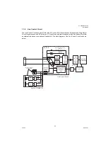
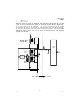
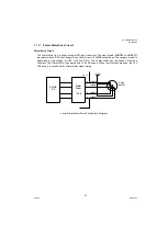
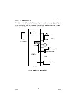
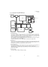
1.1.13 Laser Unit (LSU) Control Circuit
The laser control signals are described below.
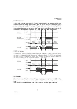
nLDEN
The LSU is activated when this output signal is LOW. If an error occurs, the nLDEN output signal level
goes High and the LSU is deactivated.
nVIDEO
This is the actual Data Signal. The Laser is ON when the nVIDEO output signal level is LOW.
nHSYNC
This horizontal synchronization signal transmitted from the Beam Detection Sensor sets the horizontal
position of the laser beam as it crosses the OPC Drum.
nSTART
This is the Scanner Motor Control Signal. The Scanner Motor rotates when the nSTART output signal
level is LOW.
nREADY
A Phased-Lock Loop (PLL) circuit keeps the Scanner Motor speed constant when the nREADY is at a
Low output signal level.
CLK
This is the Scanner Motor Clock.
nS/H
This is the Sample Hold Signal in order to adjust the Laser power. When the Laser switches on
compulsorily, the Laser Power is adjusted to a suitable level and held until the next duty cycle in order to
keep the Laser Power stable.
Laser
Timing
Sensor
Scanner
Motor
Laser
Drive
Circuit
Scanner
Motor
Drive
Circuit
IC3
SHINE
nVIDEO
nS/H
nLDON
nHSYNC
nPMON
LSU
+5V
Q24
IC34
IC35
C190
R330
C189
Q23
Q21
Q22
+5V
R328
R326
SC PCB
6
1
5
2
3
CN68
CN69
23
20
19
nPMRY
nPMCK
2
1
30
163
24
21
Laser Unit Control Circuit Block Diagram
R181
2
2
4
4
3
2
1
GND
3
2
1
3
2
1
3
2
1
Summary of Contents for Panafax UF-580
Page 170: ...DZZSM00214...


