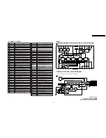
4.7.2. Service Position (2)
Turn on the power and insert the Cassette tape.
Fig. 7-2
After disconnecting the AC cord, turn over the Main C.B.A. and
Mechanism Chassis together.
Fig. 7-3
4.7.3. Service Position (3)
In Service Position (3), the DVD Main C.B.A. without Extension
Cables can be performed.
Turn on the power and playback the disc.
Fig. 7-4
4.8. HOT CIRCUIT
Primary circuit exists on the Main C.B.A.
This circuit is identified as “
HOT
” on the C.B.A. and in the
Service Manual. Use extreme care to prevent accidental shock
when servicing.
4.9. SERVICE MODE
In order to inhibit detection of the Supply & Takeup Photo
Transistors, Reel Sensor, and Cylinder Lock can be inhibited.
In this mode, Mechanism movement can be confirmed. When
removing Cassette Up Ass´y, it can be confirmed without a
cassette.
To enter Service Mode:
Press and hold FF and CH DOWN buttons on the unit together
over 5 seconds in power off condition. The unit goes into
Service Mode. The VCR and DVD LEDs blinks.
Fig. 9-1
To release from this mode, disconnect AC Plug.
14
PV-D4735S / PV-D4745 / PV-D4745S / PV-D4745S-K
Summary of Contents for OmniVision PV-D4745
Page 2: ...2 PV D4735S PV D4745 PV D4745S PV D4745S K ...
Page 10: ...Fig 1 3 2 10 PV D4735S PV D4745 PV D4745S PV D4745S K ...
Page 19: ...Fig C2 19 PV D4735S PV D4745 PV D4745S PV D4745S K ...
Page 23: ...Fig D2 23 PV D4735S PV D4745 PV D4745S PV D4745S K ...
Page 48: ...PV D4735S PV D4745 PV D4745S PV D4745S K 48 ...
Page 58: ...PV D4735S PV D4745 PV D4745S PV D4745S K 58 ...
Page 59: ...10 EXPLODED VIEWS 10 1 MECHANISM SECTION 59 PV D4735S PV D4745 PV D4745S PV D4745S K ...
Page 60: ...10 2 DVD SECTION 60 PV D4735S PV D4745 PV D4745S PV D4745S K ...
Page 61: ...10 3 CHASSIS FRAME AND CASING PARTS SECTION 61 PV D4735S PV D4745 PV D4745S PV D4745S K ...
Page 62: ...10 4 PACKING PARTS AND ACCESSORIES SECTION 62 PV D4735S PV D4745 PV D4745S PV D4745S K ...


