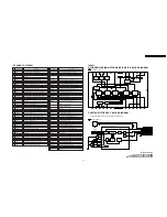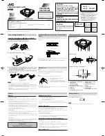
4.13. F.F.C. CONNECTION NOTE
4.13.1. F.F.C. between the Mechanism and
Main C.B.A.
Be careful with the direction of F.F.C. to Connectors as shown.
Note:
1. Insert the F.F.C. so that it is parallel to the connector.
2. After inserting the F.F.C., check that the F.F.C. does not
incline.
Fig. 13-1
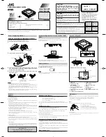
4.13.2. F.F.C. between the DVD Unit and
Main C.B.A.
Be careful with the direction of F.F.C. to Connectors as shown.
Note:
1. Insert the F.F.C. so that it is parallel to the connector.
2. After inserting the F.F.C., check that the F.F.C. does not
incline.
Fig. 13-2
4.14. HOW TO CONFIRM AUTO
CLOCK SET FEATURE
1. Connect an RF cable from the output of one unit to the input
of the test unit.
2. Select corresponding RF channels.
3. Playback a recording of P.B.S. channel including clock set
data and confirm this feature.
16
PV-D4735S / PV-D4745 / PV-D4745S / PV-D4745S-K
Summary of Contents for OmniVision PV-D4745
Page 2: ...2 PV D4735S PV D4745 PV D4745S PV D4745S K ...
Page 10: ...Fig 1 3 2 10 PV D4735S PV D4745 PV D4745S PV D4745S K ...
Page 19: ...Fig C2 19 PV D4735S PV D4745 PV D4745S PV D4745S K ...
Page 23: ...Fig D2 23 PV D4735S PV D4745 PV D4745S PV D4745S K ...
Page 48: ...PV D4735S PV D4745 PV D4745S PV D4745S K 48 ...
Page 58: ...PV D4735S PV D4745 PV D4745S PV D4745S K 58 ...
Page 59: ...10 EXPLODED VIEWS 10 1 MECHANISM SECTION 59 PV D4735S PV D4745 PV D4745S PV D4745S K ...
Page 60: ...10 2 DVD SECTION 60 PV D4735S PV D4745 PV D4745S PV D4745S K ...
Page 61: ...10 3 CHASSIS FRAME AND CASING PARTS SECTION 61 PV D4735S PV D4745 PV D4745S PV D4745S K ...
Page 62: ...10 4 PACKING PARTS AND ACCESSORIES SECTION 62 PV D4735S PV D4745 PV D4745S PV D4745S K ...


