procedure.
STEP1.REPLACE THE IC6002
1. Remove the PCB with Mechanism unit by referring the
Disassembly procedure.
2. Disconnect the AC plug and replace the IC6002.
STEP2.INPUT THE MODEL & OPTION CODE
1. Set up the applicable model code and option code by ordering the
following table.
PROCEDURE
F.I.P. DISPLAY
Turn on the Service Mode
1.Press the FF key and the
EJECT key simultaneously for
more than 3 seconds.
Activate the Service Mode 2
2.While keep placing FF key,
press the EJECT key in twice.
Activate the Entering Mode.
3.Press the EJECT key for
more than 3 seconds.
Set the Mode 2.
4.Press the CH UP key in
twice.
Display the Setting Code.
5.Press the POWER Button to
turn the power on.
(Colon starts
flashing)
Enter the Model and Option Code.
6.Service Screen is displayed on the monitor.
7.Set the applicable Model and Option code by
using REW, PLAY, STOP and FF keys on the
Remote Controller. (See Fig.S1 & S2)
Exit from Service Mode.
8.Press the POWER Button to
turn the power off.
9. Press FF and EJECT keys
simultaneously in 6 times.
(Normal Indication)
Fig. S1 Service Screen Sample for NV-VP23EP
8
Summary of Contents for NV-VP23-33
Page 13: ...C Stop unloading just before unloading would be completed D Then the tape becomes slack 13 ...
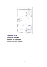
Page 22: ...7 9 MAIN PCB UNIT 1 Unscrew the Screws 2 Release the Connectors 3 Remove the Main PCB Unit 22 ...
Page 39: ...10 3 FRONT HOLDER 1 Remove the Front Holder 10 4 CLAMP PLATE UNIT 39 ...
Page 56: ...12 ABBREVIATIONS 56 ...
Page 64: ...20 1 VCR CHASSIS PARTS SECTION 20 2 DVD CHASSIS PARTS SECTION 64 ...
Page 65: ...20 3 CASING PARTS SECTION 65 ...
Page 66: ...66 ...
Page 67: ...20 4 PACKING PARTS SECTION 67 ...


