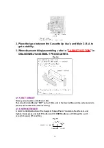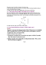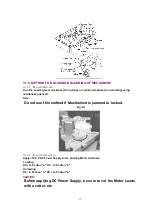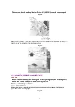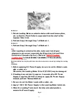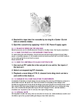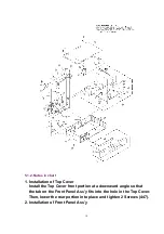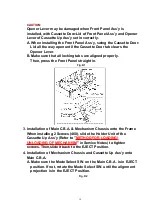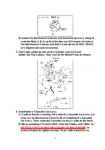
2. Place the tape between the Cassette Up Ass’y and Main C.B.A. to
get a stability.
3. When disassembling/assembling, refer to "
CABINET SECTION
" in
DISASSEMBLY/ASSEMBLY PROCEDURES.
Fig. 3-4
4.1.5. HOT CIRCUIT
Primary circuit exists on the Main C.B.A.
This circuit is identified as "HOT" on the C.B.A. and in the Service Manual. Use extreme care to
prevent accidental shock when servicing.
4.1.6. SERVICE MODE
In order to inhibit detection of the Supply & Takeup Photo Transistors, Reel Sensor, and
Cylinder Lock, press and hold FF button and CH DOWN buttons on VCR together over 5
seconds in power off condition.
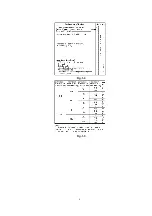
Fig. 4-1
10
Summary of Contents for NV-SJ4130PN
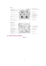
Page 6: ...Fig 1 4 Fig 1 5 6 ...
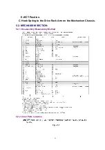
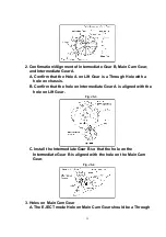
Page 22: ...5 2 3 EJECT Position Confirmation Fig J1 2 22 ...
Page 48: ...10 2 MECHANISM BOTTOM SECTION 48 ...
Page 49: ...10 3 CASSETTE UP COMPARTMENT SECTION 49 ...
Page 50: ...10 4 CHASSIS FRAME AND CASING PARTS SECTION 50 ...
Page 51: ...10 5 PACKING PARTS AND ACCESSORIES SECTION 51 ...
Page 56: ...11 2 MECHANICAL REPLACEMENT PARTS LIST MECHANICAL REPLACEMENT PARTS 56 ...
Page 96: ......
Page 97: ......


