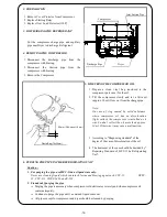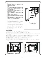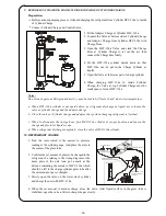
5. Close quickly the valve as soon as the set amount is charged.
6.
7.
11. LEAKAGE TEST AND RUNNING TEST
1.
Note:
2. Connect the plug with power supply.
3.
Note:
Leak detector should be the one for exclusive - use for HFC-134a.
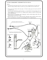
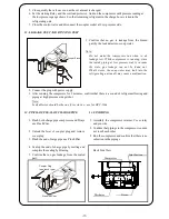
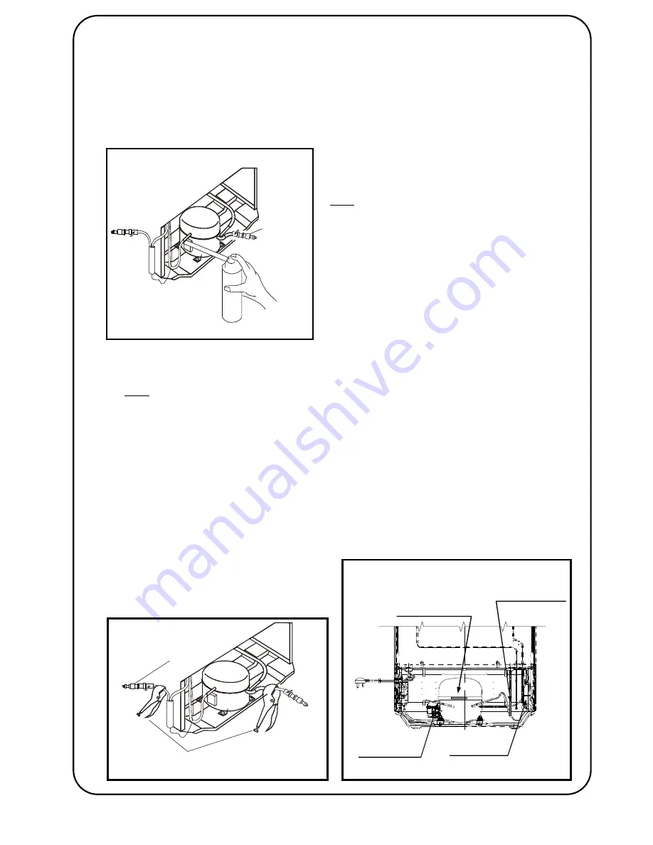
12. PINCH-OFF SEAL OF CHARGE PIPE
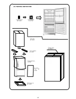
13. FINISHING
1.
1.
2.
2.
3.
3.
4.
Back Side View
5.
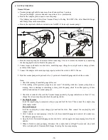
Run the compressor and confirm that there is no
vebration in the pipings.
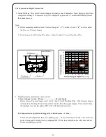
Pinch the end of carge pipe use Pinch Plier.
Seal up the end of charge pipe by melting and
complete the sealing by Brazing.
Set the starting Relay and the overload protector. And run the compressor until pressure reading at
the low pressure gauge shows 0 so that remaining refrigerant in the charge hose is taken in the
refrigerating unit.
Close the control valve and disconnect the coupler socket at Low pressure side.
Confirm that no gas is leakage from the brazed
part by the leak detector or soup water.
Confirm that no gas leakage from the sealed
part.
Do not make the compressor run when to do
leakage test. While compressor is running, since
the inside piping at low pressure side is vacuum
the state, gas leakage can not be found out.
What's worse, the soup water may leak into the
refrigerating unit and it may cause a malfunction.
After running the compressor for 3 minutes, confirm that there is a sound of refrigerant flowing and
piping at high pressure side gets hot.
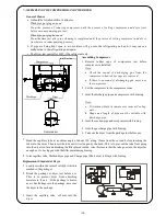
Pinch both charge pipe compressor and Draye
use Pinch Plier.
Unlock the lever of coupler plug and remove
cover plug.
Assembly the compressor retainer, Cover relay
and pin wire.
Confirm that pipings in the compressor room do
not touch each other.
Pinch-0ff Plier
Coupler Plug
(one-touch type)
Coupler Socket
Dryer
Discharge
Compressor
Joint Suction
-17-
Summary of Contents for NR-B203G-S7
Page 10: ... 9 ...
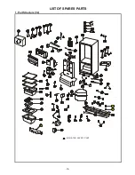
Page 22: ...1 Part Structure 1 2 LIST OF SPARES PARTS INDICATED SAFETY PART 52 90 91 19 ...
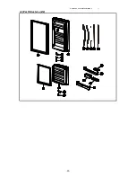
Page 23: ...PMIRF0806022AI 1 2 Part Structure 2 2 20 ...
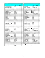
Page 26: ... 22 ...

