background image

8. VACUUM PUMPING

General Clause:

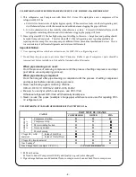
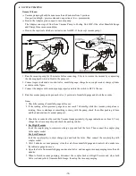
Vacuum pumping should be done more than 60 minutes from 2 portions.

One portion at high - pressure side and one portion at low - pressure side.

Be sure the Adaptor good connect to vacuum pump.

1.

2.

3.

4.

Note:

1. Check the reading of manifold gauge before use.
2.

3.

4. For High Pressure

For Low Pressure

5.

6.

7.

After 2 minutes vacuum pumping, close the valve form manifold gauge and control valve, make sure
the indicator gauge no move.

Open the Valve from manifold gauge and control valve, and one again vacuum pumping more than 60
minutes.

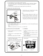
When to finish vacuum pumping, disconnect the coupler Socket at High Pressure and close both
Valve (red and yellow) from manifold Gauge. then stop the vacuum pumping.

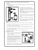
Insert the coupler plug to compressor charge pipe and lock the lever. Then connect the coupler plug
with coupler socket.

If the reading at low-pressure gauge does not reach 760 mmHg while the vacuum pump alone is
running, there is aleakage or something is wrong with the pump, check the rubber packing of hose
and the deterioration of vacuum pump oil.

Check the vacuum level by read the Vacuum Gauge periodicly, if gauge indication over from 0.5 torr,
change the oil vacuum pump and check the packing rubber.

Inert the coupler plug to dryer charge pipe and lock the lever. Then connect the coupler plug with
coupler socket.

The Adaptor can stop oil flow from Vacuum Pump to Cooling Unit HFC-134a, after Manifold Gauge
and Charge Hose vacuum condition.

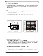
Be sure the rapir tools which are exclusive use for HFC-134a (except vacuum pump).

Run the vacuum pump for 30 minutes before connecting. This is to resume the vacuum by evaporating
the cleaning liquid which is blent in the pump oil.

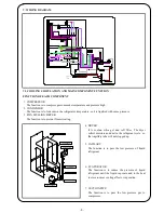
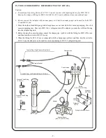
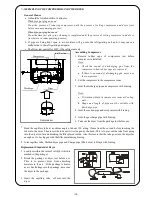
Connect repair tools such as control valve, manifold gauge, charge hose, coupler socket, charge cylinder
as shown in the figure.

Connect the adaptor with vacuum pump properly and turn the switch to HFC-134a use.

Run the vacuum pump and open each valve (3 portions) of manifold gauge and check the vacuum.

Coupler Socket

Charge cylinder

Control Valve

Manifol Gauge

Valve
 
state

open

Valve 

 state

close

Valve 

 state

close

Adaptor

Coupler plug
(one-touch type)

Coupler plug
(one-touch type)

Change Switch

HFC-134a

Low Pressure 
Gauge

High Pressure
 Gauge

Valve open  state
during vacuum pumping

Valve 

 state

during vacuum pumping

close

-15-

Summary of Contents for NR-B203G-S7

Page 1: ...ht and dimension are actual condition Matsushita Electric Industrial Co Ltd Made in Indonesia 1 Destination Malaysia NR B203G S7 Cabinet Dimension External Dimension 46 kg 50 Hz 207 Liter FC 65 Liter Universal Silver Polyurethane 40 mm 600 mm 642 mm Cooling Performance AT 32 o C 0 2 5 3 0 2 5 17 0 22 13 0 5 0 2 5 280 5 cc Freol Alpha 22 240 Volt 0 48 A Cold Colder Coldest 103 W NR B203G S7 PMIRF08...

Page 2: ...VII Repairing devices which are exclusive use for HFC 134a Refrigerant 6 VIII Repairing standard for Refrigerating Unit HFC 134a 6 IX Tool for repairing Refrigerating Unit HFC 134a 7 X Refrigerating unit repairing procedure 8 XI Manual Repairing Refrigerating Unit 9 17 XII Safety Check 18 XIII Instruction to Assembly Parts 19 XIV Part List 20 21 XV Packing Instruction 22 2 ...

Page 3: ...N II DIMENSION Crisper Cover Lamp PC Tray Anti bacteria hurb cassette Ice box Case FC Bottom Egg Shelf Free Shelf Shelf Bottle Turn Rack Grill Front Egg Tray Ice Tray Panasonic Badge Handle 515 mm 642 mm 600 0 mm 1406 mm 3 ...

Page 4: ...t the refrigerator is provided sufficient space away from the wall minimum 10 cm from the back minimum 12 cm from the sides and minimum 10 cm from the top Make sure that the refrigerator is placed on a hard and level surface to prevent vibration and Noise If one of the legs does not touch the floor adjust the adjustable leg Adjuster Bolt to stabilize it Caution Adjuster Bolt More than 10 cm More t...

Page 5: ...e room as cooling effect or vaporation PIPE MULLION DRYER CONDENSOR EVAPORATOR CAPPILARY MULLION SUCTION PIPE DRYER COMPRESSOR GREEN ORANGE PINK BLACK 0 75mm 2 BLACK 0 75mm 2 0 75mm 2 2 ROUND RECEPTACLE SUPPLY CORD 3P 240 50Hz 0 75mm 2 BROWN 0 75mm 2 0 75mm 2 BLACK PINK 0 75mm 2 YELLOW 2 WIRES BIMETAL THERMOSTAT 3 WIRES TEMP FUSE 0 75mm 2 FAN MOTOR HEATER DEFROST J3 0 5mm 2 2 1 187 M2 MOTOR MOTOR ...

Page 6: ...m pumping process Ester Oil is characteristic of higher hygroscopicity When moisture leaks into the refrigerating unit it will chemically react with the moisture and solid substance clogging the pipe will form It is also characteristic of less stability when chlorine is contain Ester oil will chemically react with refrigerants containing chlorine and solid substance clogging the piping will form S...

Page 7: ...2 and HFC 134a Since the inside of manifold gauge and charge hoses are vacuum state after vacuum pumping the oil of vacuum pumping may flow into HFC 134a refrigerant unit The adaptor prevents the oil from flowing into the refrigerating unit Before running the vacuum pump connect the charge pipe yellow with the fitting for HFC 1354a use and then turn the switch to HFC 134a use Coupler Plug High Pre...

Page 8: ...st Run Pinch off seal of charge pipes Finish IMPORTANT POINTS Refer to the TROUBLE SHOOTING For purging the pipe use HFC 134a as liquid state Never use HCFC 141b HCFC 22 for purging Do not keep the pipes open to air more than 30 minutes These process in total should be finished within 30 minutes Rubber caps should be removed just before compressor is used Never leave the compressor without the cap...

Page 9: ... Change Compressor Cooling Unit brooken Gas leakage Be found gas residu Repair gas leakage and re charge Gas nothing Spray with gas Compressor run but not compress Short time Operation fault Thermostat broken Change Thermostat Compressor running Long time Out side Evaporator Evaporator closed by frost to more Evaporator not close by frost Very Cold Touch Defrost button Cooling Unit broken Repair a...

Page 10: ... 9 ...

Page 11: ...leakage Cut capillary tube at outlet of dryer Check the smell Check compressor oil Can not repair Bad smell Occasionally frosting Frosting too much Yes Compressor broken Clog caused by solid substance Clog caused by solid substance Make compressor stop and check if gas come out by cutting capillary tube ar 35 mm from outlet of dryer Gas come out from both dryer side and evaporator side Gas come ou...

Page 12: ... running If Compressor stop start compressor again about 5 minute until stabile pressure then check pressure Before measuring make sure the Pressure Gauge at 0 position If not at 0 position adjust the Screw at Pressure Gauge Keep the gap from Pierching Plier about 4mm by adjust Screw at Pierching Plier Before release Pressure Gauge catch poit 1 dan 2 with Pierching Plier After Pressure Gauge relea...

Page 13: ... with brazing Disconnect the discharge pipe from the compressor with brazing Remove the Compressor Tilt the compressor slowly and let a little oil approx 10 ml flow out from the charge pipe On case of clog caused by solid substance whwn compressor oil has no discoloration light yellow the compressor is installed as it was So don t collect the oil more than approx 10 ml Otherwise it may case a malf...

Page 14: ...m compressor side so that no deteriorated oil can flow into the condenser Connect the charge cylinder for HFC 134a with the process tube fitting Place a container at the inlet of discharge pipe firmly When pipe cleaning at high pressure side is finished disconnect the process tube fitting from the inlet pipe of dryer Close the valve of charge cylinder when liquid come out Collect the liquid in the...

Page 15: ...lidity which is marked in the package Joint capillary tube Mullion dryer pipe and Charge pipe Dia 4 mm to Draye with brazing If there is no sound of discharging gas never use the compressor Take out the dryer from the package just before use Joint the suction pipe and compressor with brazing Note Set the compressor in the compressor room D joint must place in compreesor room at Cooling unit From t...

Page 16: ...cuum pump oil Check the vacuum level by read the Vacuum Gauge periodicly if gauge indication over from 0 5 torr change the oil vacuum pump and check the packing rubber Inert the coupler plug to dryer charge pipe and lock the lever Then connect the coupler plug with coupler socket The Adaptor can stop oil flow from Vacuum Pump to Cooling Unit HFC 134a after Manifold Gauge and Charge Hose vacuum con...

Page 17: ... by freezer burn due to low temperature Slowly open the valve on the lower sie of cylinder and charge the unit with HFC 134a When the set amount is amount charge close the valve After liquid surface in the glass tube is stabilized open the valve a little to charge the gas slowly Close the valve at Cylinder charge and adaptor charge when charging refrigerant is finished When to disconnect the charg...

Page 18: ...ct the coupler socket at Low pressure side Confirm that no gas is leakage from the brazed part by the leak detector or soup water Confirm that no gas leakage from the sealed part Do not make the compressor run when to do leakage test While compressor is running since the inside piping at low pressure side is vacuum the state gas leakage can not be found out What s worse the soup water may leak int...

Page 19: ... at 1500VAC 5 mA 1 minute Connect the high voltage cord s pin to the cabinet and switch on puncture test Connect the Service Cord pin to each other Connect the grounding pin and insulation tester to service cord of Refrigerator Connect positif pin Insulation tester to body of Refrigerating Unit Connect the Service Cord to each other Place the refrigerator on the wooden surface Connect the pin of g...

Page 20: ...d be 80 50 cN m 8 9 Install Thermo Case As to the cabinet Make sure Thermo Case As fixed properly on the cabinet Fix Thermo Case As By Truss 4TS14 1 pcs Tighthening torque should be 80 50 cN m Install Piece Duct PC Cover Lamp to the cabinet Make sure Cover Lamp fixed properly on the cabinet 11 Fix Cover lamp By Truss 4TS14 1 pcs Tighthening torque should be 80 50 cN m 10 12 Restore all Cabinet Acc...

Page 21: ...screw Truss 4TS14 1 pcs at Cover Lamp 1 pcs at Thermo Case 3 pcs at Plat Duct PC Time 34 second Release Piece Duct PC Cover Lamp Thermo Case from cabinet Time 14 second Release Plate Duct PC As from cabinet Time 5 second Additional Moran Tape 2 layers to the Plate Duct PC As Moran Tape must be fix surely at Plate Duct PC As and may not be pell off Time 5 second 1 2 3 4 5 6 18c ...

Page 22: ...1 Part Structure 1 2 LIST OF SPARES PARTS INDICATED SAFETY PART 52 90 91 19 ...

Page 23: ...PMIRF0806022AI 1 2 Part Structure 2 2 20 ...

Page 24: ... 32 CAP PAN H4TS 1 79 GASKET FC 1 33 DOOR SWITCH 1 80 DOOR AS PC FOAM S BD 318460 BD 318461 1 34 LAMP CLEAR 1 81 LATCH DOOR PC 1 35 COVER ROOM LAMP 1 82 STOPPER DOOR PC 1 36 HINGE TOP 1 83 TRUSS 5TS25 AT MC 1 37 WASHER 5X12X0 8MC 2 84 GASKET PC 1 38 HEXAGON H 5 TS 16 2 85 BASE HANDLE S 1 39 HINGE CENTER FP AE 135812 AE 136182 1 86 REINFORCE HANDLE PC 1 40 WASHER 5X12X0 8MC 2 87 HEXAGON H 5 TS 16 2...

Page 25: ...STRUCTION Refrigerator Cover OP 7186 Pallet Carton As AK 133950 Carton Box AK 124940 Top Cushion R L AK 134031 Strapping Band AJ 108740 Guarantee Card AK 125450 Instruction Book AK 137780 Ins Layer Front AK 125490 22 ...

Page 26: ... 22 ...
Reviews: