No. SX-DSV02472 -
63-
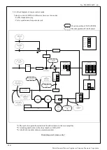
5-2-3 Block diagram of torque control mode
Velocity control of MINAS-A5B series, there are two modes.
・
Profile torque mode (tq)
・
Cyclic synchronous torque mode (cst)
+
-
Command
detection
Gain switching
2nd setup
1.14
Mode
1.24
Delay time
1.25
Level
1.26
Hysteresis
1.27
Current control
Response
setup
6.11
Main
Power
supply
Velocity detection
filter
1st
1.03
2nd
1.08
Instantaneous
speed
6.10
Notch filter
2.03
2.06
2.09
2.12
Depth
2.02
2.05
2.08
2.11
Width
1st
2.01
2nd
2.04
3rd
2.07
4th
2.10
Frequency
Velocity control
1.02
1.07
Proportion Integration
Inertia ratio
1st
1.01
2nd
1.06
0.04
Sign
Absolute value
Torque limit
Selection
5.21
MAX
6072
外部スケール
エンコーダ
モータ
Load
Encoder
Motor
6064h
<APOS>
Position actual value
[command]
60BAh
or
60BCh
<LPOS>
Touch probe
position value
[command]
Electronic gear
reverse conversion
6063h
Position actual
internal value
[Encoder pulse]
606Ch
<FSPD>
Velocity actual value
[commad/s]
6074h
Torque demand
[0.1
%
]
60B2h
<TFF>
Torque offset
[0.1%]
6080h
<VLIM>
Max motor speed
[r/min]
Velocity unit
conversion
Absolute value
Multiplication
+
+
6071h
<TQREF>
Target torque
[0.1%]
1st
0.13
2nd
5.22
Motor speed
[r/min]
Velocity limit
[r/min]
Torque command
TRQ
[0.1%]
Sum of feedback pulses
[Encoder pulse]
Torque filter
1st
1.04
2nd
1.09
2nd
6.42 6.43
At tenuation
term
*1) The symbols in parentheses indicate the abbreviations in the servo amplifier.
*2) A slanting number shows the object number of EtherCAT.
*3) A bold letter number shows a parameter number.
Block diagram of torque control
Monitor position of PANATERM
Monitor position of CiA402 object
R1.05
Motor Business Division, Appliances Company, Panasonic Corporation


