A200/A100 Hardware
Input/Output Terminals (Input/Output Ports)
3
−
12
3.7
About Grounding
3.7
About Grounding
Attaching a Ground to Prevent Effects of Noise
−
The controller can tolerate the noise present in a normal environment. Provide a
ground when installing it in a particularly noisy environment.
Use a Dedicated Ground Wire
−
Use a third
−
type ground of 0.3 to 1.25mm
2
or more and with ground resistance of
100
Ω
or less.
−
Locate the ground as close as possible to the controller and minimize the length of
the ground wire.
−
Use a dedicated ground wire in order to avoid negative effects from ground wires
shared with other devices.
Image
checker
Image
checker
Inverter and
other devices
Inverter and
other devices
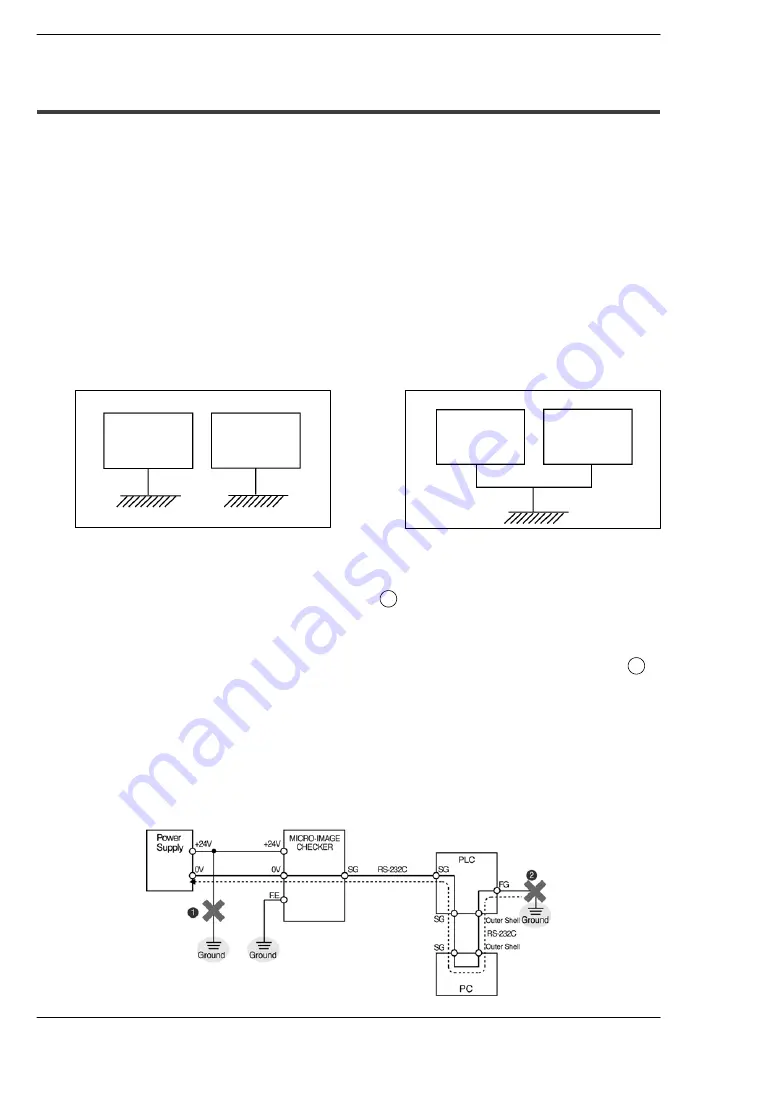
Incorrect
Correct
Note on connecting the positive terminal of the power supply to ground
−
Install another power supply for A
−
series controller. Do not connect the positive
terminal of the power supply to ground (see
1
in the drawing below).
−
Should the positive terminal of the power supply be connected to ground, do not
connect the FG terminal of an external device such as PLC, etc. because the SG
terminal of the A
−
series may be connected to ground via the FG terminal (see
2
in
the drawing below).
The SG terminal of the A
−
series is internally connected to the GND (0V) terminal.
For some computers, the SG terminal of RS232C port and the outer shell of the
connector have already been connected. In this case, the SG terminal of the
A
−
series and the FG terminal of an external device such as PLC, etc. will be
connected. If the positive terminal of the power supply to ground, a short
−
circuit
condition occurs, resulting in damaging the internal circuit.
Summary of Contents for MICRO-IMAGECHECKER A200 Series
Page 1: ......
Page 5: ......
Page 9: ...Contents A200 A100 Hardware iv...
Page 11: ...A200 A100 Hardware Part Names and Functions 1 2...
Page 19: ...A200 A100 Hardware Part Names and Functions 1 10 1 4 Keypad...
Page 21: ...A200 A100 Hardware Installation and Wiring 2 2...
Page 31: ...A200 A100 Hardware Input Output Terminals Input Output Ports 3 2...
Page 43: ...A200 A100 Hardware Serial RS 232C Ports 4 2...
Page 53: ...A200 A100 Hardware Serial RS 232C Ports 4 12 4 3 TOOL port VBT Ver 2 Port...
Page 55: ...A200 A100 Hardware About Camera Modes 5 2...
Page 59: ...A200 A100 Hardware About Camera Modes 5 6 5 3 Frame Mode and Field Mode...
Page 60: ...Chapter 6 Product Type Data Creation and Backup 6 1 Product Type Data Creation and Backup 6 3...
Page 61: ...A200 A100 Hardware Optional Memory 6 2...
Page 63: ...A200 A100 Hardware Optional Memory 6 4 6 1 Product Type Data Creation and Backup...
Page 65: ...A200 A100 Hardware General Specifications 7 2...
Page 71: ...A200 A100 Hardware General Specifications 7 8 7 5 CS Mount Camera ANM832...
Page 73: ...A200 A100 Hardware Part Numbers 8 2...
Page 85: ...A200 A100 Hardware Dimension diagram 9 2...
Page 92: ...Dimension diagram A200 A100 Hardware 9 9 9 6 Lenses ANB842NL ANM88281 ANM88041 ANM88081...
Page 93: ...A200 A100 Hardware Dimension diagram 9 10 9 6 Lenses ANM88251 ANM88161...
Page 95: ...A200 A100 Hardware Pin Assignment 10 2...
Page 98: ...Chapter 11 Manual revision history 11 1 Manual revision history 11 3...
Page 99: ...A200 A100 Hardware Manual revision history 11 2...
Page 101: ...A200 A100 Hardware Manual revision history 11 4...
Page 102: ......