11
4.6.
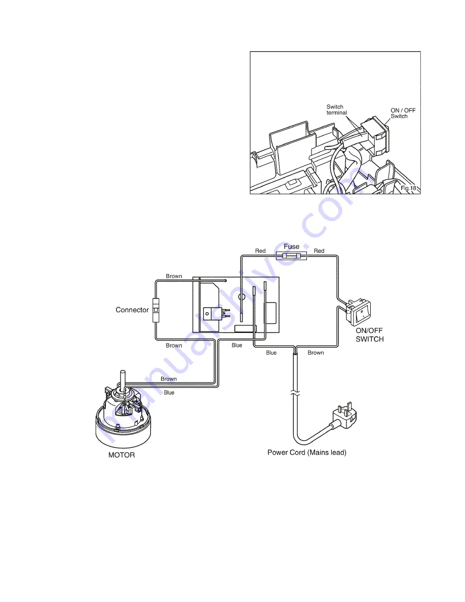
ON/OFF SWITCH
1. Remove the switch cover as described in the paragraph
"PC board w/Components, ON/OFF switch, fuse unit, and
mains power cord (lead wire)" (4.6.1).
2. Remove the two lead wires from the ON/OFF switch (with
fast-on terminal). (Fig. 18).
3. Replace the ON/OFF switch with a new one. Connect the
two lead wires to the terminal according to the schematic
diagram.
4. Restore the switch cover to its original position and refas-
ten the screws.
5 Wiring Connection Diagram
MODEL MC-E3002-WP47


