10
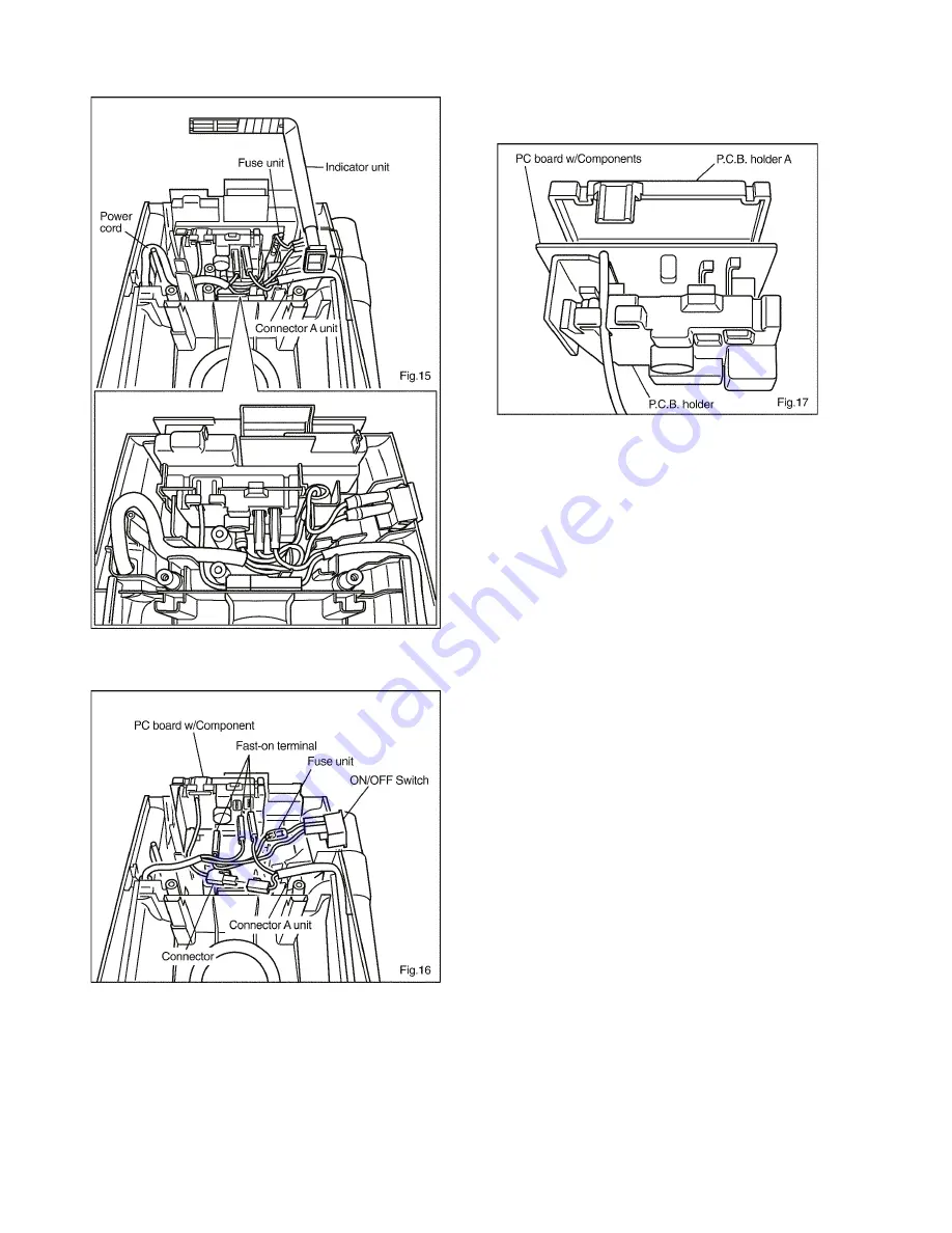
2. Remove the indicator unit (Fig. 15).
3. Lift the printed circuit board section and remove the fast-
on terminal and the connector (Fig. 16).
4. Open P.C.B. holder A and the P.C.B. holder. Remove the
PC board w/Components inside. (Fig. 17)
Note: You can remove the ON/OFF switch, fuse unit,
and mains power cord (lead wire).
5. Connect the lead wires according to the schematic dia-
gram, restore the switch cover to its original position, and
refasten the screws.
* Connection of the lead wires for assembly
Connect the lead wires as shown in Fig. 15.


