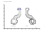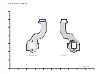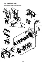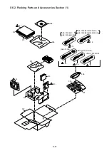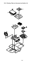
S6. Exploded View
S6.1. Frame and Casing Section
S-20
28
27
45
B11
B3
B4
30
B22
29
44
B14
B17
B19
36
11
7
6
10
3
4
5
B1
B2
9
8
12
37
15
13
B13
1
35
B23
31
2
25
24
26
19
33
43
B10
41
B8
B9
42
38
B12
B5
B24
17
39
40
16
46
14
B21
B7
B6
208
209
207
210
211
204
214
215
B15
B16
B20
205
213
212
202
203
201
B201
B202
B203
B211
B207
B208
B210
B209
B205
B206
216
23
B204
48
49
(For DMC-TZ2)
47
(For DMC-TZ3)
B25
50
Summary of Contents for Lumix DMC-TZ2P
Page 12: ...12 4 Specifications...
Page 13: ...13 5 Location of Controls and Components...
Page 14: ...14...
Page 22: ...22 8 Disassembly and Assembly Instructions 8 1 Disassembly Flow Chart 8 2 PCB Location...
Page 24: ...24 For DMC TZ2 Fig D1a 8 3 2 Removal of the LCD Unit For DMC TZ3 Fig D2 For DMC TZ2 Fig D2a...
Page 27: ...27 8 3 8 Removal of the Flash Unit Battery Frame Unit Lens Plate and Front Grip Fig D9 Fig D10...
Page 34: ...34 8 5 7 Assembly for the Zoom Motor Unit and Master Flange Unit...
Page 52: ...S 14...


