10
3.4.2.
INITIAL SETTINGS:
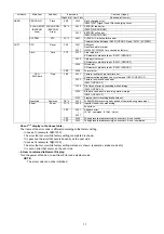
When you replace the Main PCB, be sure to perform the initial settings after achieving the adjustment by ordering the following pro-
cedure in accordance with model suffix of the unit.
1. IMPORTANT NOTICE:
Before proceeding Initial settings, be sure to read the following CAUTIONS.
2. PROCEDURES:
• Preparation. Proceed the picture back up from the unit (Refer to above "CAUTION 2")
•
Step 1. The temporary cancellation of factory setting:
Set the mode dial to “[ Normal picture mode ] (Red camera mark)”.
While keep pressing [ Optical Image Stabilizer ] and “[ UP ] of Cross key” simultaneously, turn the Power on.
•
Step 2. The cancellation of factory setting:
Set the mode dial to “[ Playback ]”.
Press [ Optical Image Stabilizer ] and “[ UP ] of Cross key” simultaneously, then turn the Power off.
•
Step 3. Turn the Power on:
Set the mode dial to “[ Normal picture mode ] (Red camera mark)”, and then turn the Power on.
•
Step 4. Display the INITIAL SETTING:
While keep pressing [ MENU ] and “[ RIGHT ] of Cross key” simultaneously, turn the Power off.
Summary of Contents for Lumix DMC-TZ2P
Page 12: ...12 4 Specifications...
Page 13: ...13 5 Location of Controls and Components...
Page 14: ...14...
Page 22: ...22 8 Disassembly and Assembly Instructions 8 1 Disassembly Flow Chart 8 2 PCB Location...
Page 24: ...24 For DMC TZ2 Fig D1a 8 3 2 Removal of the LCD Unit For DMC TZ3 Fig D2 For DMC TZ2 Fig D2a...
Page 27: ...27 8 3 8 Removal of the Flash Unit Battery Frame Unit Lens Plate and Front Grip Fig D9 Fig D10...
Page 34: ...34 8 5 7 Assembly for the Zoom Motor Unit and Master Flange Unit...
Page 52: ...S 14...


