background image


Page 25


About disposal of components containing mercury


NOTICE


This machine has a fluorescent lamp (a backlight) that contains a small amount of 
mercury. It also contains lead in some components. Disposal of these materials may 
be regulated in your community due to environmental considerations.


For disposal or recycling information please contact your local authorities, or the 
Electronics Industries Alliance.


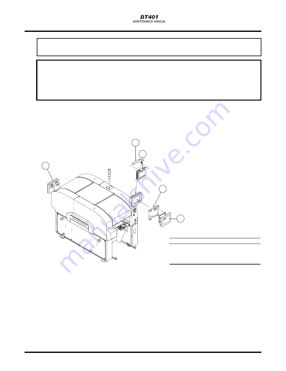
This machine has a fluorescent lamp (a backlight) built into the color touch panel.


For information on how to remove the fluorescent lamp (the backlight), refer to the “Maintenance 
Manual.”


Locations where the fluorescent lamp (the backlight) is used


Name


Color touch panel (Two lamps in use)


Fluorescent lamp (Backlight)


Screw


Cover


E64C-E-XXA00-A05-00


E64C-AE00 

3

4

1


2

Summary of Contents for KXF-E64C

Page 1: ...el No KXF E64C Maintenance Manual Thank you for purchasing DT401 the modular multi functional placement machine Before placing the machine in service be sure to read the instruction manual for proper usage After that store it carefully and read it if necessary E64C E MMAA 0006 ...

Page 2: ......

Page 3: ... 13 Nagahasu Tateishi machi Tosu city Saga Japan Phone number 81 942 84 2644 Fax number 81 942 84 2636 For Service and Supply of Spares in Europe you may contact Panasonic Europe Continental Europe PFAE Panasonic Factory Automation Europe Winsbergring 15 22525 Hamburg Germany Phone number 0049 0 40 85386 321 Fax number 0049 0 40 85386 332 United Kingdom PIEL Panasonic Industrial Europe U K Panason...

Page 4: ...cluding a direct tray Rated capacity Power source for HUB 150 VA Supply air pressure 0 49 MPa 0 78 MPa Downstream from MR unit 0 49 MPa 0 54 MPa Supply air volume 100 L min A N R Outside dimension 1260 mm W 2722 mm D 2000 mm H Including PATLITE Mass 2 1600 kg Standard configuration excluding a collectively changing truck Environmental condition Temperature 10 C to 35 C Humidity 25 to 60 No condens...

Page 5: ... of Operations Manual Programming Manual Reference Manual Maintenance Manual and Installation Manual These manuals describe the operations programming detailed functions routine maintenance inspections and much more E64C E MMA00 A01 00 ...

Page 6: ...he machine describing operating instructions precautions and the other information you should note Maintenance Manual This manual is organized for the persons who maintain the machine describing simple checks adjustments and replacement of consumable parts And also troubleshooting is described Programming Manual This manual is organized for the engineers who program the production data of the line...

Page 7: ...escription T Symbols used in this manual In this manual the following symbols are used for description Shows pressing a key on the touch panel Shows an operation flow Shows a reference item UNLOCK o START Means pressing UNLOCK and then START within 2 seconds Engineer Shows the operation for an engineer A B Means pressing B key with A key held down Operator Shows the operation for an operator 3 2 4...

Page 8: ...fter Operation 1 34 1 4 Every 140 Hour Check Once a Week 1 35 1 4 1 Cleaning the Color Touch Panel 1 35 1 4 2 Cleaning the Transfer Head 1 36 1 4 3 Cleaning Support Pins Collectively Changing Tables 1 44 1 4 4 Cleaning Line Camera Cover Glass 1 47 1 4 5 Cleaning the Line Camera Lens Cover Glass 1 48 1 4 6 Cleaning the Tape Feeder Installation Surface 1 49 1 5 Every 560 Hour Check Once a Month 1 50...

Page 9: ...guration 2 5 2 1 4 Operation Parameter Configuration 2 10 2 1 5 Nozzle Changer 2 11 2 1 6 Heat Correction Mark 2 12 2 1 7 Mount Position 2 12 2 1 8 Board Positioning 2 13 2 1 9 Plane Correction 2 13 2 1 10 Network 2 14 2 1 11 Camera 2 15 2 1 12 Light Quantity 2 15 2 1 13 Pick up Position 2 16 2 1 14 Status Indicator Lamp 2 16 2 1 15 Each Angle Head Position 2 17 2 1 16 Head Rotation Center 2 17 2 ...

Page 10: ... 31 3 2 3 CPU Box Temperature Abnormality 3 32 3 2 4 Board Recognition Error 3 32 3 2 5 SSR Ready Error 3 34 3 2 6 Drop in Voltage 3 35 3 2 7 Bad Nozzle Detected Bad Nozzle Rate Over 3 41 3 2 8 Pick up Errors Drop of Chips 3 42 3 3 Load Arrangement Drawings 3 43 3 3 1 Common 3 43 3 3 2 Multi Functional Head Type 3 46 3 4 Load Lists 3 47 3 4 1 Motor List 3 47 3 4 2 SOL List 3 48 3 4 3 Sensor List P...

Page 11: ...9 INDEX PERIODIC CHECK LIST APPENDIX 1 I O MAP 1 1 DT401 F 1 2 DT40S 20 OPTION 1 3 DT45T 40 OPTION APPENDIX 2 AIR CIRCUIT DIAGRAM APPENDIX 3 MATERIAL SAFETY DATA SHEET E64C E MMA00 A02 00 ...

Page 12: ...10 MEMO E64C E MMA00 A02 00 ...

Page 13: ...ath or serious injury WARNING This indication refers to a situation which is considered that there is a possibility of death or serious injury CAUTION This indication refers to a situation which is considered that there is a possibility of only injury or physical damage The matters that shall be observed are classified by the symbols as shown below and described The following are the examples of t...

Page 14: ...Page 2 DANGER E64C E XXA00 A03 01 ...

Page 15: ... abnormal state an accident or a breakdown will occur DT401 F has two emergency stop buttons Pressing any one of them stops operation Press the nearest one Eliminate the cause of danger or abnormality and then restart operation To reset pull the emergency stop button Emergency stop button At the rear side M107 Emergency stop button At the front side E64C E XXA00 A03 00 ...

Page 16: ...er and stop the air supply Lock the power supply switch and the main air valve Changeover or working for daily check Setting the nozzles in the nozzle changer Maintenance of the inside of the machine Turn OFF the servo switch and then open the safety cover Turn OFF the servo switch and then open the safety cover Cut off the power supplying to this machine Rear panel OFF ON SERVO STOP UNLOCK STEP S...

Page 17: ...o the floor where is 120 mm or more away from around the machine in order to draw a distinct line between the operator area and the maintenance area see Fig 2 We recommend that you should keep away from the most protrudent part guide for feeder cart of the machine by 120 mm or more outside of the area with yellow and black stripes as indicated by Fig 2 Guide for feeder cart Fig 1 Color Yellow Blac...

Page 18: ... of the receipt of unloaded boards Normally we cannot look inside the opening for unloading because the machine is installed close to the next machine in whole line If however you use it on a standalone basis it is possible We recommend you to add a buffer stocker to the unloading side Board flow direction Do not look inside Machine s side view E PW0106M1 E64C E XXA00 A03 01 ...

Page 19: ...g parts in the machine We recommend that you fill the truck with feeders or dummy ones so that you will not accidentally put your hands into the machine M114 Avoid working with the conveyor cover opened Your hands may potentially be injured by the moving parts in the machine Cover M115 E64C E XXA00 A03 00 E64C 011E E64C 010E E64C AC00 ...

Page 20: ...ric shock Even if the power supply switch is turned OFF in maintenance the power is still supplied as far as the primary line of the power supply switch therefore you may potentially receive an electric shock M111 E64C AC00 L1 L2 L3 PE 4Z4C 825E E64C E XXA00 A03 01 ...

Page 21: ...Page 9 WARNING E64C E XXA00 A03 01 ...

Page 22: ...Page 10 WARNING E64C E XXA00 A03 00 ...

Page 23: ...Page 11 WARNING E64C E XXA00 A03 00 ...

Page 24: ...Page 12 CAUTION E64C E XXA00 A03 00 ...

Page 25: ...Page 13 CAUTION E64C E XXA00 A03 01 ...

Page 26: ...ine as follows Follow the instructions on each label If it has come off place an order with us for it referring to the Parts List then put a new one on a proper location Label No Warning label locations on the front side Warning label locations on the rear side E64C E XXA00 A04 01 E64C 012E E64C 013E ...

Page 27: ...ls are pasted on this machine as follows Follow the instructions on each label If it has come off place an order with us for it referring to the Parts List then put a new one on a proper location Label No Warning label locations on the front side E64C 003E E64C E XXA00 A04 01 ...

Page 28: ...els are pasted on this machine as follows Follow the instructions on each label If it has come off place an order with us for it referring to the Parts List then put a new one on a proper location Label No Warning label locations on the rear side E64C 004E E64C E XXA00 A04 01 ...

Page 29: ...ls are pasted on this machine as follows Follow the instructions on each label If it has come off place an order with us for it referring to the Parts List then put a new one on a proper location Label No Warning label locations on the front side E64C 014E E64C E XXA00 A04 01 ...

Page 30: ...his servo switch is turned OFF all of the drive shafts of the machine will be inactive For information about the operations above refer to the instruction manuals for each model Lock out tagout procedure Lock out tag out for each maintenance is required It is described as Turn OFF the power and air in each manual Tag Key is should be control in your tag procedure We recommend a engineer by trainin...

Page 31: ...tor prevents picked up components from dropping Since it is installed inside the frame there is no danger that workers may receive an electric shock or become entangled with it Motor for the vacuum pump The other motors see below stop if an emergency stop button is pressed 1 XY axis motor 2 Zθ axis motor 3 Conveyor motor 4 Width adjustment motor E64C E XXA00 A04 01 E64C AA00 E64C 009E ...

Page 32: ... of the line camera Item LED specifications Manufacturer Panasonic Factory Solutions Co Ltd Model number KXFK001LA00 Wavelength 850 nm Output 5 32 mJ Class Class 1 Emission duration 6 2 sec Maximum Installation location See the left figure 2 Laser The laser unit can be installed at the front and the rear of the machine This unit is optional The maximum output of the laser components used in the la...

Page 33: ...erased or may not be loaded owing to an improper handling Be sure to back up the program and data in order to guard against the loss of data Backup means making an identical copy of a floppy disk For information on how to back up see the disk copy procedure under file operations 2 Write Protection It is possible to mechanically protect the stored data from an accidental erasure or rewrite Write pr...

Page 34: ...ticularly the magnetic substance inside the disk Automatic shutter Avoid placing heavy objects on the disk Avoid applying an excessive force to the disk Avoid storing and leaving the disk in areas exposed to the following conditions Avoid using such a case as is not provided for storage and carrying High or low temperature High humidity Dusty Direct sunlight Floppy disk Case While the disk drive a...

Page 35: ...l plate The serial plate indicating the product name and production number of the machine is pasted on the following location Actually is replaced with a numeric value E64C E XXA00 A05 02 E64C AB00 DT401 F KXF E64C ...

Page 36: ...it Before disposing of it be sure to purge the air Locations where the air spring is used Removing air spring Turn the hexagon socket head cap screw counterclockwise and remove the spring Disposing of air spring Drill a hole in the spring and purge the air from it completely Range to drill the air spring 15 mm to 20 mm 1B4C 442E 3 E64C AC00 1D4C 406E 2 1 E64C E XXA00 A05 01 ...

Page 37: ...derations For disposal or recycling information please contact your local authorities or the Electronics Industries Alliance This machine has a fluorescent lamp a backlight built into the color touch panel For information on how to remove the fluorescent lamp the backlight refer to the Maintenance Manual Locations where the fluorescent lamp the backlight is used Name Color touch panel Two lamps in...

Page 38: ...Page 26 MEMO E64C E XXA00 A05 00 ...

Reviews: