background image

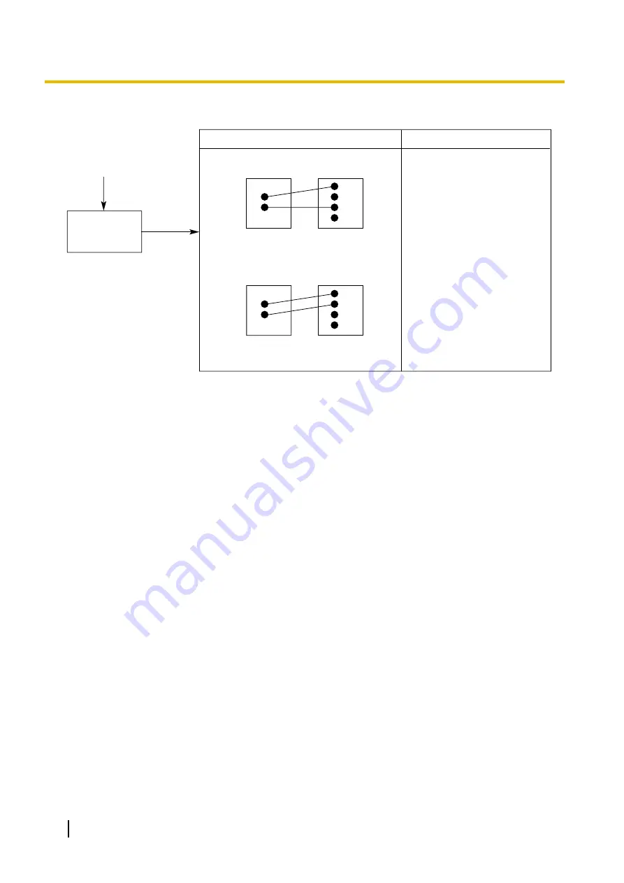
Connection between the trunk and the PBX:

CAUSE

Trunk is connected to the T2/T1.

SOLUTION

Reconnect the trunk to 
the T1/R1 or T2/R2 of the 
telephone jack using 2-
conductor wiring.

T2
R1
T1
R2

Trunk

PBX

Trunk is connected to the T2/R1.

PBX

Trunk

T2
R1
T1
R2

No

Can you dial 
out on a 
trunk?

(Continued from the 
previous page.)

186

Installation Manual

5.1.2 Connection

Summary of Contents for KX-TDE200

Page 1: ...llation Manual SD Logo is a trademark Thank you for purchasing a Panasonic Pure IP PBX Please read this manual carefully before using this product and save this manual for future use KX TDE100 KX TDE2...

Page 2: ...hone IP PT KX NCS4208 8 Channel IP Softphone IP Proprietary Telephone Activation Key 8 IP Softphone IP PT KX NCS4216 16 Channel IP Softphone IP Proprietary Telephone Activation Key 16 IP Softphone IP...

Page 3: ...tion Key for CA PRO for 5 Users CA Pro 5users KX NCS2210 Activation Key for CA PRO for 10 Users CA Pro 10users KX NCS2240 Activation Key for CA PRO for 40 Users CA Pro 40users KX NCS2249 Activation Ke...

Page 4: ...PRI23 KX TDA0484 4 Channel VoIP Gateway Card IP GW4E KX TDA0490 16 Channel VoIP Gateway Card IP GW16 Physical Extension Cards KX TDA0143 4 Cell Station Interface Card CSIF4 KX TDA0144 8 Cell Station...

Page 5: ...IF Card for 2 4 GHz Portable Station KX TDA0151 2 Channel Cell Station Unit Using a DHLC DLC Card PTinterface CS for 2 4 GHz Portable Station KX TDA0152 3 Channel Cell Station Unit Using a CSIF Card f...

Page 6: ...ephones and DSS consoles KX TD7500 DECT portable station Note For the equipment e g Add on Key Module USB Module Headset 1 that can be connected to a particular telephone refer to the telephone s manu...

Page 7: ...s are not available for certain countries areas Consult your certified Panasonic dealer for detailed instructions In this manual the suffix of each model number e g KX TDE100NE is omitted unless neces...

Page 8: ...could result in death or serious injury CAUTION This notice means that misuse could result in injury or damage to property List of Abbreviations APT Analogue Proprietary Telephone CA Communication As...

Page 9: ...g Do not use the product near water for example near a bathtub wash bowl kitchen sink or laundry tub in a wet basement or near a swimming pool Avoid using wired telephones during an electrical storm T...

Page 10: ...les used If outlets power strips extension cords etc are used in a manner that exceeds their rated capacity they emit large amounts of heat which could cause a fire Unplug the product from the wall ou...

Page 11: ...lectricity by touching ground or wearing an earthing strap Failure to do so may cause the PBX to malfunction due to static electricity When driving the screws into the wall be careful to avoid touchin...

Page 12: ...retrieved from it 6 To prevent data leakage render the SD Memory Card physically unusable before disposal 7 When user information is sent from the PBX to a PC or other external device the confidentia...

Page 13: ...iring code as shown below If in any doubt please consult a qualified electrician WARNING This appliance must be earthed IMPORTANT The wires in the mains lead are coloured as follows Green and yellow E...

Page 14: ...scard electrical and electronic equipment please contact your dealer or supplier for further information Information on Disposal in other Countries outside the European Union These symbols are only va...

Page 15: ...ACCESS TO OTHER CARRIERS FOR TOLL CALLS When calling back a number from the Caller ID list all numbers prefixed with 0 AREA CODE will be automatically forwarded to your toll carrier This includes num...

Page 16: ...ith this Installation Manual the following manuals are available Feature Guide Describes all basic optional and programmable features of the PBX PC Programming Manual Provides step by step instruction...

Page 17: ...on 59 3 2 7 Installing Removing the Optional Service Cards 61 3 2 8 Types of Connectors 66 3 2 9 Attaching a Ferrite Core 68 3 2 10 Fastening an Amphenol Connector 71 3 2 11 Wall Mounting KX TDE200 73...

Page 18: ...Cabling Distances of the Extension Wiring Twisted Cable 145 3 8 2 Parallel Connection of the Extensions 147 3 8 3 Digital EXtra Device Port Digital XDP Connection 150 3 8 4 First Party Call Control CT...

Page 19: ...3 6 1 Revision History 194 6 1 1 PMMPR Software File Version 2 0xxx 194 6 1 2 PMMPR Software File Version 2 01xx 195 6 1 3 PMMPR Software File Version 3 0xxx 196 Index 197 Installation Manual 19 Table...

Page 20: ...20 Installation Manual Table of Contents...

Page 21: ...Section 1 System Outline This section provides general information on the PBX including the system capacity and specifications Installation Manual 21...

Page 22: ...ontrolling the PBX To use the system install a power supply unit PSU in the PSU Slot and optional service cards in the basic shelf KX TDE100 KX TDE200 Construction of the Basic Shelf A PSU Slot B Free...

Page 23: ...X T7633 PC USB APT DPT ISDN Telephone Amplifier CTI Server PC PC SLT DSS Console DSS Console KX T7600 KX T7600 External Sensor External Relay Device IP PT IP Softphone CA 3 Client PC SIP Extension Pri...

Page 24: ...IP EXT16 KX TDA0470 IP GW4E KX TDA0484 IP GW16 KX TDA0490 CS PS Doorphone Door Opener Station Message Detail Recording SMDR PC SLT Wireless Phone Fax Machine Mountable Equipment Router Radio Amplifier...

Page 25: ...t of 140 4 W Safety Class 1 compliant KX TDA0108 S Type Power Supply Unit PSU S Power Supply Unit for the KX TDE100 Total power output of 74 W Safety Class 1 compliant KX TDA0143 4 Cell Station Interf...

Page 26: ...with 4 power failure transfer PFT ports KX TDA0182 8 Port DID Card DID8 8 port DID trunk card KX TDA0183 4 Port Analogue Trunk Card LCOT4 4 port analogue trunk card with 2 power failure transfer PFT...

Page 27: ...ISDN ETSI compliant KX TDA0290CJ PRI Card PRI30 1 port ISDN Primary Rate Interface card 30B channels EURO ISDN ETSI compliant KX TDA0290 PRI Card PRI23 1 port ISDN Primary Rate Interface card 23B cha...

Page 28: ...l Pulse DP 10 pps 20 pps Tone DTMF Dialling Extension Dial Pulse DP 10 pps 20 pps Tone DTMF Dialling Mode Conversion DP DTMF DTMF DP Ring Frequency 20 Hz 25 Hz selectable Trunk Loop Limit 1600 W maxim...

Page 29: ...face CS 1 pair wire D1 D2 PT interface CS High density 4 pair wire D1 D2 DSS Console and Add on Key Module 1 pair wire D1 D2 Dimension KX TDE100 334 mm W 390 mm H 272 mm D KX TDE200 430 mm W 415 mm H...

Page 30: ...Flash Recall Timing Range 24 ms to 2032 ms BRI Cards Internal ISDN Mode Supply Voltage 40 V Power Supply BRI4 4 5 W per 1 line 10 W per 4 lines Power Supply BRI8 4 5 W per 1 line 20 W per 8 lines Powe...

Page 31: ...imum Number KX TDE100 KX TDE200 IPCMPR Card Slot 1 1 Free Slot 6 11 Virtual Slot Virtual Trunk Slot 4 4 Virtual Extension Slot 4 4 IPCMPR Card Slot and Free Slots KX TDE100 KX TDE200 A B C B A Free Sl...

Page 32: ...m Optional Service Cards The following number of cards can be installed in the Free Slots or Virtual Slots of the PBX Note Any card that exceeds the capacity of the PBX will be ignored When the PBX st...

Page 33: ...LC8 SLC16 CSLC16 MSLC16 IP EXT16 CSIF4 CSIF8 OPB3 IPCMPR 4 Total 6 Total 8 Trunk Card Card Type Maximum Number Virtual Trunk Card Total 8 Physical Trunk Card Total 6 Total Virtual Extension Card Physi...

Page 34: ...SG4 4 4 ESVM2 ESVM4 EIO4 4 4 1 Only 1 ECHO16 card can be mounted on each OPB3 card Maximum Trunks and Extensions The PBX supports the following number of trunks and extensions Type KX TDE100 KX TDE200...

Page 35: ...ension 1 Only 49 virtual trunk extension card channels can be in use at any one time except for peer to peer calls for IP extensions Note For non peer to peer calls via the DSP card calls cannot be ma...

Page 36: ...IP PT 2 supported by IPCMPR card 128 128 SIP Extension 128 128 DSS console 8 8 CS 32 3 32 3 2 to 4 channel CS 32 32 High density CS 16 16 IP CS 16 16 PS 128 128 Voice Processing System VPS 2 2 Doorph...

Page 37: ...tion Calculate the load figure from the type and number of items of equipment to be connected and determine the type of PSU that will be required Load Figure Calculation Equipment Type Load Figure PT...

Page 38: ...600 series DPT 48 units 48 Other DPT 2 units 8 SLC16 1 card 16 MSLC16 1 card 16 VPS 8 ports 8 Total 96 The total load figure is 96 As this is between 64 and 128 you should install the PSU M But if you...

Page 39: ...Section 2 Activation Key Installation This section describes information on activation keys including how to obtain an activation key and install it in the SD Memory Card Installation Manual 39...

Page 40: ...IP softphones 4 IP Softphone IP PT 2 Allows the use of 4 IP PTs IP softphones 32 8 IP Softphone IP PT 2 Allows the use of 8 IP PTs IP softphones 16 16 IP Softphone IP PT 2 Allows the use of 16 IP PTs...

Page 41: ...talled activation key to be used for H 323 trunks through system programming By default all the installed activation keys will be used for SIP trunks 2 You can set how many IP softphones can be used w...

Page 42: ...X NCS4102 2 IP Trunk 30 60 IP trunks H 323 SIP 24 48 IP trunks H 323 SIP KX NCS4104 4 IP Trunk 15 12 Activation Keys for IP Telephones Model No Activation Key Type Maximum Number Supported IP Telephon...

Page 43: ...s 3 120 users KX NCS2149 CA Basic 128users 1 128 users KX NCS2201 CA Pro 1user 128 128 users KX NCS2205 CA Pro 5users 25 125 users KX NCS2210 CA Pro 10users 12 120 users KX NCS2240 CA Pro 40users 3 12...

Page 44: ...IP Trunk 8 Channel IP Proprietary Telephone 8 Channel IP Softphone IP Proprietary Telephone 16 Channel SIP Extension IPCMPR Card Virtual Slots Virtual Trunk Slots Virtual Extension Slots SD Memory Car...

Page 45: ...n only download the activation key file once using the activation key number and registration ID provided on the activation key code Up to 8 activation keys can be downloaded as one activation key fil...

Page 46: ...e transferring files to the SD memory card the PBX automatically renames them according to the header information A message will be displayed when the transfer is complete 4 Click OK 5 Under Configura...

Page 47: ...e PBX Detailed instructions for planning the installation site installing the shelves and optional service cards and cabling of peripheral equipment are provided Further information on system expansio...

Page 48: ...t install the system in the following locations WARNING Areas where shocks or vibrations are frequent or strong Such activity may lead to the product falling over and causing injury or may impair the...

Page 49: ...ce when wiring and plug the system back in only after all wiring is completed Trunks should be installed with surge protectors For details refer to 3 2 14 Surge Protector Installation Notice Use 2 pai...

Page 50: ...a Ferrite Core 1 1 2 1 2 Metal Bracket 1 1 Screw A 3 4 Screw B Black 2 6 Anchor Plug 3 4 Mini Plug for pager and music source 4 4 SD Memory Card 1 1 1 In Canada there is no ferrite core attached to t...

Page 51: ...J E I H A RUN Indicator B ALARM Indicator C MNT Port D LAN Port E PSU Slot F Null Slot not available for any optional service card G Free Slots 1 to 6 from the left H IPCMPR Card Slot I RS 232C Port...

Page 52: ...screwdriver into the opening on the left of the screw cover and unlatch the screw cover Screw Cover 2 Turn the screw anticlockwise to loosen 3 Slide the front cover to the right until it stops then l...

Page 53: ...lide the front cover to the left until it locks 2 Turn the screw clockwise to tighten 3 Secure the screw cover 1 2 CAUTION For safety reasons close the front cover and tighten the screw before operati...

Page 54: ...PSU M or KX A229 for PSU L WARNING Each PSU complies with Safety Class 1 of IEC60950 EN60950 UL60950 CAN CSA C22 2 No 60950 and AS NZS60950 therefore a protective earth connection exists between the...

Page 55: ...a PSU only Do not replace or remove the PSU for any other purpose Installing the Power Supply Unit 1 Insert the PSU along the guide rails CAUTION For safety reasons do not touch parts in the PSU Guide...

Page 56: ...numbers 1 to 4 to fix the PSU 1 3 2 4 Screws Replacing the Power Supply Unit 1 Unplug the AC power cord and Back up Battery Cable 2 Turn the 4 screws anticlockwise to loosen them Screws 56 Installati...

Page 57: ...f the arrow to disconnect the PSU from the back board Release Lever Back Board 4 Replace the PSU New PSU Current PSU 5 Follow the steps in Installing the Power Supply Unit Installation Manual 57 3 2 4...

Page 58: ...he AC cable has an effect against external noise and lightning strikes but it may not be enough to protect the PBX A permanent connection between earth and the earth terminal of each PBX must be made...

Page 59: ...correct type of Back up Battery Cable for the PSU Notice Be sure to comply with applicable local regulations e g laws guidelines Note Turn on the battery switch on the PSU only after the installation...

Page 60: ...y switch on the PSU 2 Connect the Back up Battery Cable to a set of 3 identical batteries Back up Battery Cable Backup Batteries VRLA 12 V DC x 3 Red Fuse Battery Connector Black Battery Switch 60 Ins...

Page 61: ...ing the IPCMPR card the DC power supply must be turned off Note The optional service cards can be installed or removed while the DC power is supplied Installing Optional Service Cards 1 Insert the car...

Page 62: ...Turn the 2 screws clockwise to fix the card in place Screws Note Make sure the screws are tightened to earth the card securely 62 Installation Manual 3 2 7 Installing Removing the Optional Service Car...

Page 63: ...h slot in which no optional service card is installed by using a Blank Slot Cover CAUTION Failure to install the Blank Slot Cover may cause electromagnetic interference Installation Manual 63 3 2 7 In...

Page 64: ...X run the cables to either the right or the left and then towards the back of the shelf as shown below 3 4 1 2 Note For safety reasons do not stretch bend or pinch the AC power cord 64 Installation Ma...

Page 65: ...ise to loosen them Screws 2 Pull the release lever in the direction of the arrow to disconnect the card from the back board Pull the card from the shelf to remove it Release Lever Back Board Installat...

Page 66: ...TDA0188 BRI4 KX TDA0284 BRI8 KX TDA0288 PRI30 KX TDA0290CE KX TDA0290CJ PRI23 KX TDA0290 IP EXT16 KX TDA0470 IP GW4E KX TDA0484 IP GW16 KX TDA0490 BNC 1 2 E1 KX TDA0188 PRI30 KX TDA0290CE KX TDA0290C...

Page 67: ...r Used for 10 pin Terminal Block 8 pin Terminal Block 8 1 10 1 DPH4 KX TDA0161 DPH2 KX TDA0162 EIO4 KX TDA0164 RS 232C 9 5 6 1 Basic Shelf Shielded cable Mini Plug 2 4 IPCMPR Installation Manual 67 3...

Page 68: ...ing to an RJ45 Connector For the IPCMPR Card Wrap the cable once around the ferrite core then close the case of the ferrite core Attach the ferrite core 3 cm away from the connector The ferrite core i...

Page 69: ...e core is included with the card When only 1 or 2 cables are used for connection wrap the cable s once around the ferrite core When 3 or 4 cables are used for connection simply pass the cables through...

Page 70: ...en close the case of the ferrite core Attach the ferrite core 3 cm away from the connector The ferrite core is included with the card 3 cm If you need to open the ferrite core use a flathead screwdriv...

Page 71: ...w to fix the upper part and use Velcro tape to fix the lower part of the connector Type A Spring Latch Velcro Tape Type B Screw Velcro Tape Velcro Tape Velcro Tape 2 1 2 2 1 Spring Latch 1 Spring Latc...

Page 72: ...rt for all optional service cards that use the Amphenol connector For more details refer to the appropriate section in 3 5 Information about the Physical Trunk Cards and 3 6 Information about the Phys...

Page 73: ...hat the openings on the back of the shelf will not be blocked Make sure that the surface behind the shelf is not made of wood Notice When placing the metal bracket make sure that the TOP arrow is poin...

Page 74: ...Metal Bracket Wall Screw A Screw A Metal Bracket Hammer Anchor Plug Drive the screw to this point 2 Hook the shelf onto the metal bracket making sure that the shelf slides down and onto the hooked par...

Page 75: ...hat the openings on the back of the shelf will not be blocked Make sure that the surface behind the shelf is not made of wood Notice When placing the metal bracket make sure that the TOP arrow is poin...

Page 76: ...acket Screw A Anchor Plug Wall Screw A Metal Bracket Hammer Anchor Plug Drive the screw to this point 2 Hook the shelf onto the metal bracket making sure that the shelf slides down and onto the hooked...

Page 77: ...and free of obstacles so that the openings on the back of the shelf will not be blocked Make sure that the surface behind the shelf is not made of wood 1 Install 4 anchor plugs in the floor using the...

Page 78: ...et slide it backwards until it locks and retain it with 2 screws B Screws B Metal Bracket FRONT TOP 1 2 4 Fix the front cover on the shelf refer to 3 2 3 Opening Closing the Front Cover 78 Installatio...

Page 79: ...protect the system from electrical surges we strongly recommend connecting the system to a surge protector that meets the following specifications Surge arrestor type 3 electrode arrestor DC spark ove...

Page 80: ...e CS If you install an extension outside of the building the following precautions are recommended a Install the extension wire underground b Use a conduit to protect the wire Note The surge protector...

Page 81: ...ire should be as short as possible 3 The earthing wire should run straight to the earth rod Do not run the wire around other objects 4 Bury the earth rod at least 50 cm underground Note The above figu...

Page 82: ...s LAN connection so that IP telephones IP PTs IP softphones SIP Extensions and PCs can be connected on a private IP network Mountable Cards Either one of the DSP16 or DSP64 cards refer to 3 3 2 DSP16...

Page 83: ...es on the IPCMPR card Alternatively ESVM2 ESVM4 cards mounted on an OPB3 card already support these features Use only the SD Memory Card included with the PBX The SD Memory Card must be inserted in th...

Page 84: ...MNT 2 LINK Green Link status indication OFF Off line ON Linked normally Flashing In communication 100 Yellow Data transmission speed indication OFF 10 Mbps ON 100 Mbps LAN 1 LINK Green Link status ind...

Page 85: ...and G 711 codec methods To be mounted on the IPCMPR card DSP16 Card DSP64 Card Screw inside Accessories and User supplied Items Accessories included Screws 3 User supplied not included none Note Depen...

Page 86: ...When installing the DSP16 or DSP64 card hold down the shaded areas of the card to connect it firmly 86 Installation Manual 3 3 2 DSP16 Card KX TDE0110 and DSP64 Card KX TDE0111...

Page 87: ...3 Utility File Transfer PBX SD Card to PC in the PC Programming Manual After installing the IPCMEC card the PBX must be initialised For details about the initialisation procedure refer to 3 13 1 Start...

Page 88: ...te communication with the PBX ITU T V 90 support To be mounted on the IPCMPR card inside RMT Card Screw IPCMPR Card Accessories and User supplied Items Accessories included Screws 2 User supplied not...

Page 89: ...nk Card V SIPGW16 Virtual Card for 16 channel SIP trunk Compliant with RFC 3261 3262 3264 3311 3581 3960 and 4028 protocols and ITU T G 729AB and G 711 codec methods Also supports T 38 protocol Virtua...

Page 90: ...FT ports A maximum of 2 CID8 cards 2 CID PAY8 cards or one of each can be mounted on the LCOT16 card refer to 3 5 3 CID PAY8 Card KX TDA0189 and 3 5 4 CID8 Card KX TDA0193 Amphenol To trunk LED Access...

Page 91: ...ng port 13 38 TM Tip port 13 14 RN Ring port 14 39 TN Tip port 14 15 RO Ring port 15 40 TO Tip port 15 16 RP Ring port 16 41 TP Tip port 16 17 2 5 Reserved 42 5 0 Reserved Note Pin assignments for the...

Page 92: ...ms Accessories included Screws 2 User supplied not included Amphenol connector Note To connect the Amphenol connector refer to 3 2 10 Fastening an Amphenol Connector To confirm the trunk connection re...

Page 93: ...t 5 6 RF Ring port 6 31 TF Tip port 6 7 RG Ring port 7 32 TG Tip port 7 8 RH Ring port 8 33 TH Tip port 8 9 25 Reserved 34 5 0 Reserved LED Indications Indication Colour Description CARD STATUS Green...

Page 94: ...tches for ports 09 16 at OFF positions LCOT16 card only OFF ON OFF ON ON OFF ON OFF SW2 SW2 Ports 09 16 Ports 01 08 SW1 SW1 Accessories and User supplied Items Accessories included Screws 2 User suppl...

Page 95: ...ccessories and User supplied Items Accessories included Screws 2 User supplied not included none Note Only 1 CID8 card can be mounted on the LCOT8 card Switch Settings on LCOT8 LCOT16 cards Switch Typ...

Page 96: ...nnector refer to 3 2 10 Fastening an Amphenol Connector To confirm the trunk connection refer to Confirming the Trunk Connection in 3 13 1 Starting the PBX Pin Assignments Amphenol Connector No Signal...

Page 97: ...3 R1F Ring 1 port 6 19 EF E line port 6 44 MF M line port 6 20 TG Tip port 7 45 RG Ring port 7 21 T1G Tip 1 port 7 46 R1G Ring 1 port 7 22 EG E line port 7 47 MG M line port 7 23 TH Tip port 8 48 RH R...

Page 98: ...s Notice When connecting the RJ45 connector attach the included ferrite core except in Canada where the ferrite core is not necessarily required Refer to 3 2 9 Attaching a Ferrite Core Note This optio...

Page 99: ...Indication Colour Description CARD STATUS Green Red Card status indication OFF Power Off Green ON Normal all ports are idle Green Flashing 60 times per minute Normal a port is in use Red ON Fault incl...

Page 100: ...d ON Synchronised Flashing 60 times per minute Synchronised Clock Master Maximum Cabling Distance of Extension Connection The maximum length of the extension cable that connects the T1 cards is shown...

Page 101: ...to the trunk directly E1 ports are SELV ports and should only be connected to SELV services Notice When connecting the RJ45 connector attach the included ferrite core Refer to 3 2 9 Attaching a Ferri...

Page 102: ...outer conductor Connection of 1 and 2 Open default Connection of 2 and 3 Short Pin Assignments RJ45 Connector for Trunk Use No Signal Name Level V Function 8 1 1 RX Receive data 2 RX Receive data 3 Re...

Page 103: ...chronisation status indication OFF Normal ON Out of synchronisation RAI Red RAI signal status indication OFF Normal ON Alarm Clock Slave Flashing 60 times per minute Alarm Clock Master AIS Red AIS sta...

Page 104: ...re to do so may cause damage to the power supply circuit of the BRI4 BRI8 card or the terminal When connecting these optional service cards to the trunk connect through an NT1 do not connect to the U...

Page 105: ...tor for Extension Use No Signal Name Level V Function 8 1 1 2 Reserved 3 RX2 Receive data 2 4 TX1 Transmit data 1 5 TX2 Transmit data 2 6 RX1 Receive data 1 7 8 Reserved LED Indications Indication Col...

Page 106: ...details Note LINE 5 to LINE 8 are for BRI8 card only LINE LED Pattern Layer 1 Layer 2 Master Clock LED Pattern OFF OFF OFF 1 s ON OFF OFF 1 s ON ON OFF 1 s ON OFF ON 1 s ON ON ON 1 s Layer 1 ON Synchr...

Page 107: ...cts the PBX and the ISDN terminal equipment TE is shown below TE CAT 5 Under 1000 m CAT 5 Under 150 m CAT 5 Under 50 m CAT 5 Under 500 m TE 1 TE 1 TE 8 TE 8 Point to Point Point to Multipoint Expansio...

Page 108: ...rts and should only be connected to SELV services Notice When connecting the RJ45 connector attach the included ferrite core Refer to 3 2 9 Attaching a Ferrite Core Note In some countries areas this o...

Page 109: ...evel V Function 8 1 1 RX Receive data 2 RX Receive data 3 Reserved 4 TX Transmit data 5 TX Transmit data 6 8 Reserved RJ45 Connector for Extension Use No Signal Name Level V Function 8 1 1 TX Transmit...

Page 110: ...ication OFF Normal ON Alarm Clock Slave Flashing 60 times per minute Alarm Clock Master AIS Red AIS status indication OFF Normal ON Alarm SYNC Green Synchronisation status indication OFF Not synchroni...

Page 111: ...hould only be connected to SELV services Notice When connecting the RJ45 connector attach the included ferrite core except in Canada where the ferrite core is not necessarily required Refer to 3 2 9 A...

Page 112: ...dication Colour Description CARD STATUS Green Red Card status indication OFF Power Off Green ON Normal all ports are idle Green Flashing 60 times per minute Normal a port is in use Red ON Fault includ...

Page 113: ...inute Synchronised Clock Master D LINK Green Data link status indication OFF Not established ON Established Maximum Cabling Distance of Extension Connection The maximum length of the extension cable t...

Page 114: ...e IP GW4E card occupies the space of only 1 free slot when it is installed in the PBX For programming instructions and other information about the IP GW4E card refer to the documentation for the IP GW...

Page 115: ...indication ON On line mode OFF Off line mode Flashing Maintenance mode Note If the LINK indicator is OFF the ONLINE indicator will also be OFF ALARM Red Alarm indication OFF Normal ON Alarm VoIP BUSY...

Page 116: ...m When connecting the RJ45 connector attach the included ferrite core Refer to 3 2 9 Attaching a Ferrite Core For programming instructions and other information about the IP GW16 card refer to the doc...

Page 117: ...indication ON On line mode OFF Off line mode Flashing Maintenance mode Note If the LINK indicator is OFF the ONLINE indicator will also be OFF ALARM Red Alarm indication OFF Normal ON Alarm VoIP BUSY...

Page 118: ...rmation in the PC Programming Manual If there is a CS in out of service OUS status make sure that it is securely connected to the CSIF card If the CS remains in OUS status there may be a fault with th...

Page 119: ...ed LED Indications Indication Colour Description CARD STATUS Green Red Card status indication OFF Power Off Green ON Normal all ports are idle Green Flashing 60 times per minute Normal a port is in us...

Page 120: ...Ferrite Core To connect the Amphenol connector refer to 3 2 10 Fastening an Amphenol Connector For details about power failure transfer refer to 3 12 1 Power Failure Connections Pin Assignments Amphen...

Page 121: ...rved 19 RG SLT Ring port 7 44 TG SLT Tip port 7 20 D2G PT Data port 7 Low 45 D1G PT Data port 7 High 21 Reserved 46 Reserved 22 RH SLT Ring port 8 47 TH SLT Tip port 8 23 D2H PT Data port 8 Low 48 D1H...

Page 122: ...e To connect the Amphenol connector refer to 3 2 10 Fastening an Amphenol Connector Pin Assignments Amphenol Connector No Signal Name Function No Signal Name Function 50 25 26 1 1 Reserved 26 Reserved...

Page 123: ...port 8 Low 48 D1H Data port 8 High 24 25 Reserved 49 50 Reserved LED Indications Indication Colour Description CARD STATUS Green Orange Red Card status indication OFF Power Off Green ON Normal all por...

Page 124: ...3 2 10 Fastening an Amphenol Connector Pin Assignments Amphenol Connector No Signal Name Function No Signal Name Function 50 25 26 1 1 D2A Data port 1 Low 26 D1A Data port 1 High 2 D2B Data port 2 Low...

Page 125: ...Data port 15 High 16 D2P Data port 16 Low 41 D1P Data port 16 High 17 25 Reserved 42 50 Reserved LED Indications Indication Colour Description CARD STATUS Green Orange Red Card status indication OFF P...

Page 126: ...cluded Screws 2 Ferrite core 1 User supplied not included Amphenol connector Note Attach the included ferrite core to the cable Refer to 3 2 9 Attaching a Ferrite Core To connect the Amphenol connecto...

Page 127: ...TE Tip port 5 14 15 Reserved 39 40 Reserved 16 RF Ring port 6 41 TF Tip port 6 17 18 Reserved 42 43 Reserved 19 RG Ring port 7 44 TG Tip port 7 20 21 Reserved 45 46 Reserved 22 RH Ring port 8 47 TH T...

Page 128: ...D signals to extension ports To be mounted on the SLC8 card only EXT CID Card Screw SLC8 Card inside Accessories and User supplied Items Accessories included Screws 2 User supplied not included none 1...

Page 129: ...fer PFT ports LED Amphenol To extensions Accessories and User supplied Items Accessories included Screws 2 Ferrite core 1 User supplied not included Amphenol connector Note Panasonic SLT with Message...

Page 130: ...10 11 RK Ring port 11 36 TK Tip port 11 12 RL Ring port 12 37 TL Tip port 12 13 RM Ring port 13 38 TM Tip port 13 14 RN Ring port 14 39 TN Tip port 14 15 RO Ring port 15 40 TO Tip port 15 16 RP Ring...

Page 131: ...not included RJ45 connector Note The maximum length of the cable to be connected to this optional service card is 100 m When connecting the RJ45 connector attach the included ferrite core Refer to 3...

Page 132: ...is in use an IP PT is connected OFF No ports are in use no IP PTs are connected Note If the LINK indicator is OFF the ONLINE indicator will also be OFF ALARM Red Alarm indication OFF Normal ON Alarm V...

Page 133: ...ded none WARNING A lithium battery is used in OPB3 card There is a risk of explosion if the battery is replaced with the incorrect type Dispose of used batteries according to the manufacturer s instru...

Page 134: ...gs To door openers To doorphones 10 pin 8 pin Accessories and User supplied Items Accessories included Screws 3 10 pin terminal block 1 8 pin terminal block 1 User supplied not included Copper wire No...

Page 135: ...transmit 6 com2 Doorphone 2 receive 7 DP1 Doorphone 1 transmit 8 com1 Doorphone 1 receive 10 pin Terminal Block No Signal Name Function 10 1 1 2 Reserved 3 OP4b Door opener 4 4 OP4a Door opener 4 com...

Page 136: ...openings To doorphones door openers 10 pin 8 pin Accessories and User supplied Items Accessories included Screws 3 10 pin terminal block 1 8 pin terminal block 1 User supplied not included Copper wir...

Page 137: ...eceive 7 Call_1b RT b 1 Doorphone 1 call button 8 Call_1a RT a 1 Doorphone 1 call button com 10 pin Terminal Block No Proprietary Signal Name Standard Signal Name Function 10 1 1 2 Reserved Reserved 3...

Page 138: ...Path_1b DC1b DC1a OP1b OP1a 8 7 6 5 4 3 2 1 L O U B 12V 8V TO 0 V BL Light RT Call Button OP Door Opener Connection Terminal DC Doorphone Current Supply Control Terminal Path Doorphone Call Path Spea...

Page 139: ...To external sensors 10 pin 8 pin Accessories and User supplied Items Accessories included Screws 3 10 pin terminal block 1 8 pin terminal block 1 User supplied not included Copper wire Note For detai...

Page 140: ...om 5 C2b Control 2 6 C2a Control 2 com 7 C1b Control 1 8 C1a Control 1 com 10 pin Terminal Block No Signal Name Function 10 1 1 2 Reserved 3 OP4b Opener 4 4 OP4a Opener 4 com 5 OP3b Opener 3 6 OP3a Op...

Page 141: ...air of sensor and common lines are connected to the EIO4 card for each external sensor The PBX detects input from the sensor when the signal is under 100 W Connection Diagram External Sensor sensor co...

Page 142: ...plied Items Accessories included Screws 3 User supplied not included none Note To establish a conference call involving 6 to 8 parties install an ECHO16 card and enable echo cancellation for conferenc...

Page 143: ...4 channel message card To be mounted on the OPB3 card Screw MSG4 Card OPB3 Card inside Accessories and User supplied Items Accessories included Screws 3 User supplied not included none Installation Ma...

Page 144: ...may cause severe damage to the ESVM card Notice When replacing an ESVM card ensure that the status of the OPB3 card is In Service INS and then initialise the ESVM card For details about the initialisa...

Page 145: ...0 6 mm 360 m CAT 5 229 m Cable Maximum Distance 0 4 mm 698 m 0 5 mm 1128 m 0 6 mm 1798 m CAT 5 1128 m SLT Other PT DPT APT and DSS Console PT interface CS KX DT300 Series DPT Cable Maximum Distance 0...

Page 146: ...indicates that the extension card supports the terminal 146 Installation Manual 3 8 1 Maximum Cabling Distances of the Extension Wiring Twisted Cable...

Page 147: ...th APT For parallel connection eXtra Device Port XDP mode must be disabled for that port through system programming Refer to 1 11 9 Parallelled Telephone and 2 1 1 Extension Port Configuration in the...

Page 148: ...or further information Using a Modular T Adaptor To DHLC8 card SLT DPT Modular T Adaptor 4 conductor wiring cord Connect pins D1 and D2 2 conductor wiring cord Connect pins T and R Using an EXtra Devi...

Page 149: ...ring cord Connect pins T R D1 and D2 TO MAIN UNIT PABX TO TEL With Other DPT except KX T7560 and KX T7565 To DHLC8 card DPT SLT To DHLC8 card To SLT 2 conductor wiring cord Connect pins T and R 4 cond...

Page 150: ...ough system programming parallel connection is not possible Refer to 1 11 9 Parallelled Telephone and 2 1 1 Extension Port Configuration in the Feature Guide for further information With KX DT300 Seri...

Page 151: ...ct pins T R D1 and D2 To DLC8 DLC16 card To DHLC8 card for connection of SLT To SLT Slave DPT Master DPT Cable Maximum Distance 0 4 mm 30 m 0 5 mm 50 m 0 6 mm 60 m CAT 5 50 m Back View of DPTs To DLC8...

Page 152: ...PT Modular T Adaptor 4 conductor wiring cord Connect pins D1 and D2 2 conductor wiring cord Connect pins T and R Slave DPT Master DPT TO MAIN UNIT PABX TO TEL TO MAIN UNIT PABX Cable Maximum Distance...

Page 153: ...ct pins T R D1 and D2 Slave DPT Master DPT To SLT TO MAIN UNIT PABX TO TEL TO TEL TO MAIN UNIT PABX Cable Maximum Distance 0 4 mm 30 m 0 5 mm 50 m 0 6 mm 60 m CAT 5 50 m Back View of DPTs To DLC8 DLC1...

Page 154: ...2 conductor wiring cord Connect pins T and R Slave DPT Master DPT TO MAIN UNIT PABX TO DIGITAL TO MAIN UNIT PABX Cable Maximum Distance 0 4 mm 30 m 0 5 mm 50 m 0 6 mm 60 m CAT 5 50 m Back View of DPTs...

Page 155: ...cord Connect pins T R D1 and D2 Slave DPT Master DPT To SLT TO MAIN UNIT PABX TO TEL TO DIGITAL TO MAIN UNIT PABX Cable Maximum Distance 0 4 mm 30 m 0 5 mm 50 m 0 6 mm 60 m CAT 5 50 m Back View of DP...

Page 156: ...4 conductor wiring cord Connect pins T R D1 and D2 TO DIGITAL TO MAIN UNIT PABX TO TEL Back View of DPTs Cable Maximum Distance 0 4 mm 30 m 0 5 mm 50 m 0 6 mm 60 m CAT 5 50 m To DLC8 DLC16 card To DHL...

Page 157: ...Module must be connected to the DPT Note The operating system of the PC required for first party call control depends on your CTI application software For details refer to the manual for your CTI app...

Page 158: ...oor openers external sensors and external relays are user supplied Maximum Cabling Distance Doorphone Door Opener Cable Maximum Distance 0 4 mm 70 m 0 5 mm 113 m 0 6 mm 180 m CAT 5 113 m External Sens...

Page 159: ...ds of screws are included with the doorphone Please choose the appropriate kind for your wall type when a doorphone plate has been fixed to the wall when you wish to install the doorphone directly ont...

Page 160: ...openers external sensors and external relays Refer to 3 7 2 DPH4 Card KX TDA0161 3 7 3 DPH2 Card KX TDA0162 and 3 7 4 EIO4 Card KX TDA0164 for pin assignments Doorphone Door Opener External Sensor Ex...

Page 161: ...m 10 m 0 6 mm 10 m CAT 5 10 m 2 m RS 232C MNT Port PC via MNT Port A PC can be connected to the PBX via the MNT port of the IPCMPR card It is used for system programming diagnostics and external syste...

Page 162: ...nter via RS 232C The PBX is equipped with an RS 232C interface This interface provides communication between the PBX and the user supplied devices such as PC or line printers The RS 232C port is used...

Page 163: ...ceive Data RXD input Conveys signals from the printer or the PC Transmit Data TXD output Conveys signals from the unit to the printer or the PC A Mark condition is held unless data or BREAK signals ar...

Page 164: ...or the PC is ready to receive data from the unit The unit does not attempt to transfer data or receive data when circuit CS CTS is OFF Frame Ground FG Connects to the unit frame and the earth ground c...

Page 165: ...ould be a 10BASE T 100BASE TX CAT 5 or higher cable Make sure that all the CAT 5 cables in use are not over 100 m in length Make sure to create a spanning tree for LAN connection in order to prevent l...

Page 166: ...Power Failure Connections Analogue trunk cards LCOT16 4 PFT ports LCOT8 2 PFT ports and LCOT4 2 PFT ports Extension cards MSLC16 4 PFT ports CSLC16 4 PFT ports SLC16 4 PFT ports DHLC8 2 PFT ports and...

Page 167: ...4 1 R4 Ring port 4 2 R3 Ring port 3 3 T3 Tip port 3 4 T4 Tip port 4 RJ11 Connector Pin Assignments for Extension Card PFT Ports 1 and 2 No Signal Name Function 1 4 1 T2 Tip port 2 2 T1 Tip port 1 3 R1...

Page 168: ...at ON positions Accessories and User supplied Items Accessories included none User supplied not included RJ45 connectors Switch Settings Switch Type Usage and Status Definition PFT Setting DIP Set all...

Page 169: ...Pin Assignments No Signal Name Level V Function 8 1 1 2 Reserved 3 RX2 Receive data 2 4 TX1 Transmit data 1 5 TX2 Transmit data 2 6 RX1 Receive data 1 7 8 Reserved Installation Manual 169 3 12 1 Powe...

Page 170: ...ave started the PBX and if you unplug the PBX do not perform the following procedures to start the PBX again Otherwise your programmed data is cleared To restart the PBX refer to 5 1 4 Using the Reset...

Page 171: ...so be initialised Therefore the built in ESVM card feature may not be used for up to 2 minutes after the PBX starts LED Indications Indication Colour Description RUN Green PBX status indication OFF Po...

Page 172: ...172 Installation Manual 3 13 1 Starting the PBX...

Page 173: ...Section 4 Guide for the Maintenance Console Explains the installation procedure structure and basic information of the Maintenance Console Installation Manual 173...

Page 174: ...PBX To programme and administer the PBX by PC you need to install the Maintenance Console onto the PC This section describes overview and installation of the Maintenance Console only System Menu Menu...

Page 175: ...s must be assigned to the PC For information about fixed IP addresses ask your network administrator Note For pin assignments and maximum cabling distance refer to 3 10 1 Connection of Peripherals Ser...

Page 176: ...6 Pin No 3 2 20 6 CAUTION To protect the system keep the following in mind 1 Make sure that both connector cases frame ground of the RS 232C straight cable shielded cable are conductive If they are no...

Page 177: ...nabling automatic answer etc can only be programmed by Maintenance Console AT F is stored as the default value For more information about the AT command refer to the external modem s instructions Inst...

Page 178: ...maximum protection against unauthorised access For a list of numbers and characters that can be used in system passwords refer to 1 1 2 Entering Characters in the PC Programming Manual Installing the...

Page 179: ...n 3 13 1 Starting the PBX and restart the PBX c Repeat step 5 to reconnect the Maintenance Console to the PBX 8 Follow the instructions of the Quick Setup wizard and assign the basic items Quick Setup...

Page 180: ...emove the SD Memory Card while power is supplied to the PBX Doing so may cause the PBX to fail to start when you try to restart the system 180 Installation Manual 4 3 1 Installing and Starting the Mai...

Page 181: ...Section 5 Troubleshooting This section provides information on the PBX and telephone troubleshooting Installation Manual 181...

Page 182: ...wanted firewall in the IP network IP PTs SIP Extensions do not operate IP EXT DSP card malfunction Replace the corresponding card IPCMPR card malfunction Replace the IPCMPR card be sure to turn off th...

Page 183: ...r 5 minutes plug the PBX back in and turn the power switch back on IPCMEC card malfunction See the error log using the Maintenance Console refer to 5 1 5 Troubleshooting by Error Log If the error no 4...

Page 184: ...card be sure to turn off the PBX when replacing Poor connection Make sure that an 8 pin twisted pair cable is used for connection Make sure that none of the CAT 5 cables in use are over 100 m in leng...

Page 185: ...CAUSE SOLUTION If a telephone equipped with an A A1 relay is connected to the PBX set the A A1 relay switch of the telephone to OFF Use the correct cord the inner 2 wires are for T R PBX The T R is c...

Page 186: ...SOLUTION Reconnect the trunk to the T1 R1 or T2 R2 of the telephone jack using 2 conductor wiring T2 R1 T1 R2 Trunk PBX Trunk is connected to the T2 R1 PBX Trunk T2 R1 T1 R2 No Can you dial out on a t...

Page 187: ...e DHCP and re enter settings as appropriate Whenever you try to make calls using a SIP Extension a busy tone is heard The status of the port that the SIP Extension is connected to is Out of Service Ch...

Page 188: ...1 20 2 Flexible Buttons in the Feature Guide The KX HGT100 does not work properly or some features cannot be performed using the KX HGT100 The firmware of the KX HGT100 and the MPR software file vers...

Page 189: ...eared Calls on hold are terminated Calls on exclusive hold are terminated Calls in progress are terminated Call park is cleared Other data stored in memory except the above are not cleared Be aware th...

Page 190: ...le Station Message Detail Recording SMDR 04 01 01 10 37AM MJ ALM 000 10000 MPR WDT overflow 04 01 01 11 07AM MN ALM 010 10000 AC power down 04 01 01 03 55PM MN ALM 301 10501 Digital trunk RAI receptio...

Page 191: ...Slots 05 to 08 Virtual Extension Slots ZZ Port number For optional service cards except OPB3 card Port number 01 to 16 will be displayed For OPB3 card Sub slot number 1 to 3 port number 1 to 4 will b...

Page 192: ...192 Installation Manual 5 1 5 Troubleshooting by Error Log...

Page 193: ...Section 6 Appendix Installation Manual 193...

Page 194: ...fied Voice Message Card ESVM2 KX TDA0194 4 Channel Simplified Voice Message Card ESVM4 KX TDA0155 DECT 6 0 2 Channel Cell Station Unit Using a DHLC DLC Card PT interface CS for DECT 6 0 Portable Stati...

Page 195: ...hone IP PT KX NCS4216 16 Channel IP Softphone IP Proprietary Telephone Activation Key 16 IP Softphone IP PT KX NCS4102 2 Channel IP Trunk Activation Key 2 IP Trunk KX NCS4504 4 Channel IP Proprietary...

Page 196: ...NCS2249 Activation Key for CA PRO for 128 Users CA Pro 128users KX NCS2301 Activation Key for CA ACD Monitor for 1 ICD Supervisor CA Supervisor 1user KX TDE0105 IPCMEC memory expansion card to increa...

Page 197: ...Index Installation Manual 197...

Page 198: ...Channel SIP Extension Activation Key KX NCS4708 43 8 Port Analogue Trunk Card KX TDA0180 26 90 8 Port BRI Card KX TDA0288 27 104 8 Port Caller ID Card KX TDA0193 26 95 8 Port Caller ID Pay Tone Card...

Page 199: ...Activation Key for CA PRO for 40 Users 43 KX NCS2249 Activation Key for CA PRO for 128 Users 43 KX NCS2301 Activation Key for CA ACD Monitor for 1 ICD Supervisor 43 KX NCS4102 2 Channel IP Trunk Activ...

Page 200: ...Expansion Card KX TDE0105 25 87 MOH 162 MSG4 Card KX TDA0191 143 MSLC16 Card KX TDA0175 129 M Type Power Supply Unit KX TDA0104 25 54 N Names and Locations 51 O OPB3 Card KX TDA0190 133 Optional 3 Slo...

Page 201: ...tion 187 Troubleshooting Using the Reset Button 189 Trunk Connection 171 U Unpacking 50 V V IPCS4 Virtual 4 IP Cell Station Interface Card 89 V IPEXT32 Virtual 32 Channel VoIP Extension Card 89 V IPGW...

Page 202: ...P 2048 kbit s digital structured leased lines D2048S Panasonic Communications Co Ltd Panasonic Communications Company U K Ltd declares that this equipment is in compliance with the essential requireme...

Page 203: ...Installation Manual 203 Notes...

Page 204: ...ications Co Ltd Panasonic Communications Co Ltd 2009 KK0607EK5099 For Future Reference Please print record and retain the following information for future reference The serial number of this product c...

Reviews: