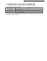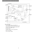
8.1.1.1. AC Input ~ PFC Output
This section explains about the operations of AC filter circuit, Rectifier circuit and PFC circuit.
1) Filter Circuit, Rectifier Circuit 1
The filter part eliminates the noise from power supply unit not to leak it out, and also the circuit prevents an incoming noise.
Varistor Z2 deals with the excessive surge voltage from thunder, etc.
Rectifier circuit 1 rectifies input AC voltage at D1, which is input to PFC circuit. Varistors Z3 and Z4 deal with the excessive
surge voltage from thunder, etc.
Refer to Fig.1 (A), (B), (C)
2) PFC Switching Circuit
Rectified input voltage at D1 is boosted by the switching operation of transformer L4, FET Q2, diode D10, and smoothed by
electrolytic capacitor C30.
The voltage between both terminals of C30 becomes PFC output voltage (DC390V TYP.).
Refer to Fig.1 (D)
17
KX-TDA0103XJ / KX-TDA0104XJ / KX-TDA0108XJ / KX-TDA0103X / KX-TDA0104X / KX-TDA0108X
Summary of Contents for KX-TDA0103XJ
Page 133: ...MEMO 133 KX TDA0103XJ KX TDA0104XJ KX TDA0108XJ KX TDA0103X KX TDA0104X KX TDA0108X ...
Page 141: ...MEMO 141 KX TDA0103XJ KX TDA0104XJ KX TDA0108XJ KX TDA0103X KX TDA0104X KX TDA0108X ...
Page 145: ...memo 145 KX TDA0103XJ KX TDA0104XJ KX TDA0108XJ KX TDA0103X KX TDA0104X KX TDA0108X ...
Page 151: ...MEMO 151 KX TDA0103XJ KX TDA0104XJ KX TDA0108XJ KX TDA0103X KX TDA0104X KX TDA0108X ...


