13 CIRCUIT OPERATION
13.1. Bell Detector Circuit
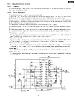
When the bell signal is input between T/R, the signal are outputted at the speaker via the following path: Tel line
→
R1/C1
→
D1
→
Pin 1 of IC1
→
Pin 8 of IC1
→
C6
→
T1
→
C625
→
Speaker
13.2. Line Interface
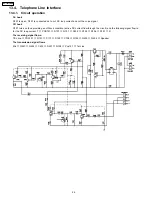
In talk status, L1 RLY output from pin 25 of IC801 changes to low level, causing Q103, Q101 to turn on and resulting in a line
loop.The loop current flows from D101(+)
→
Q101
→
Q108
→
R124
→
D106 in that order, A pulse signal that repeated
switches between high and low logic is output from pin 26 of the CPU.This switches the line loop on and off, generating the dial
pulse signal.
22
KX-T2375MXW
Summary of Contents for KX-T2375MXW
Page 3: ...1 LOCATION OF CONTROLS 3 KX T2375MXW ...
Page 4: ...2 DISPLAY 4 KX T2375MXW ...
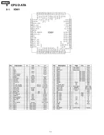
Page 16: ...8 CPU DATA 8 1 IC801 16 KX T2375MXW ...
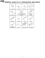
Page 18: ...9 TERMINAL GUIDE OF IC S TRANSISTORS AND DIODES 18 KX T2375MXW ...
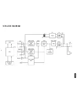
Page 19: ...10 BLOCK DIAGRAM KX T2375MXW 19 ...
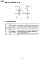
Page 20: ...11 BLOCK DIAGRAM IC 1 11 1 Communication ICs 20 KX T2375MXW ...
Page 29: ...15 CABINET AND ELECTRICAL PARTS LOCATION 29 KX T2375MXW ...
Page 30: ...16 ACCESSORY AND PACKING MATERIALS 30 KX T2375MXW ...
Page 35: ...18 1 MEMO 35 KX T2375MXW ...
Page 38: ...38 KX T2375MXW ...
Page 39: ...41 KX T2375MXW K KXT2375MXW Printed in Japan ...

