24
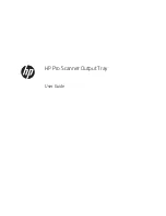
(Flowchart)
CONTROL Board
7.5.5
STARTING SENSOR
Board
7.5.7
Feed tray
Top Cover
Front cover
AC Inlet Cover
Exit tray (Assy)
Paper Tray
LCD PANEL Board
(KV-S10XXC)
Back cover
7.2.1
7.2.6
7.2.3
7.2.5
7.2.4
7.2.2
7.2.7
7.2.7
7.2.5
START
Exterior
Upper Chassis
PANEL SWITCH Board
(KV-S10XXC)
PANEL Board
(KV-SL10XX)
Scanning Glass (B)
AUTO/MANUAL
DETECTION Board
ULTRASONIC SENSOR
(G) BOARD
PAPER SENSOR
Board
Free Roller
CIS (B)
7.3.5
7.3.4
Reference plate (F)
7.3.6
7.3.3
7.3.2
7.3.7
Double Feed
Prevention Roller
7.3.1
7.3.5
Scanning Glass (F)
DOOR DETECTION
Board
Side Plate Assembly
Paper Feed Roller
7.4.2
7.4.4
7.4.5
CIS (F)
7.4.2
7.4.1
Lower Chassis
Platen Motor
Power Supply
FAN
Conveyer Motor
7.5.2
Bottom Plate
7.5.1
7.5.4
7.5.3
7.5.6
Reference plate (B)
Exit Roller
(Assy)
Conveyor roller
(Assy)
7.4.3
7.4.7
7.4.6
Summary of Contents for KV-S1027C
Page 7: ...7 ...
Page 9: ...9 3 Location of Controls and Components 3 1 Main Unit ...
Page 10: ...10 ...
Page 16: ...16 5 Section Views 5 1 Motor 5 2 Roller ...
Page 17: ...17 5 3 Board and Sensor ...
Page 31: ...31 7 3 8 Wiring of Upper Chassis ...
Page 128: ...128 14 Exploded View and Replacement Parts List ...
Page 133: ...133 14 3 Feed Tray Assembly 302 305 302 303 307 301 306 305 302 304 Feed Tray Assembly ...
Page 188: ...Index 74 8 Operating Manual Table of Contents ...
Page 255: ...PNQX6995ZA DD0914HS0 Panasonic System Networks Co Ltd 2014 ...