70
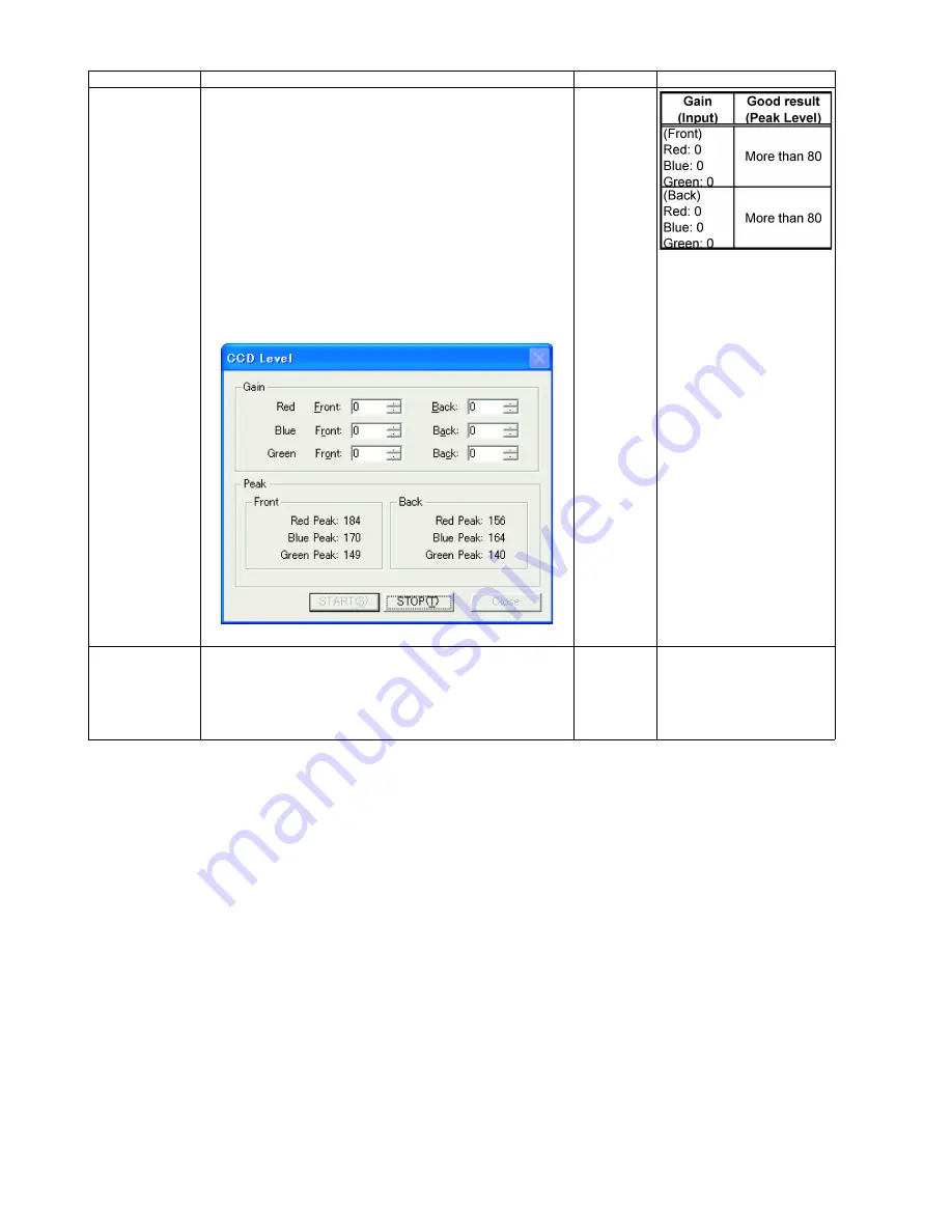
CCD Level
1. Click
“CCD Level”
on the main menu.
2. Push the Door Open Button to open the ADF Door.
And hold a sheet of clean white paper (A4 (80g/m
2
) or Letter
(20lb.)) between the Scanning Glasses (F)&(B), and then
close the ADF Door.
3. Set
“Gain”
values
of each color on the
“CCD Level”
dialog
box.
4. Click
“START”
on the
“CCD Level”
dialog box to start CCD
Level Test.
5. Check whether the peak level is within the specification.
(See Remarks.)
6. Click
“STOP”
to finish this test.
7. Click
“Close”
to get back to the main menu.
8. Open the ADF Door, and then remove the paper.
—
Memory
1. Click
“Memory”
on the main menu.
2. Click
“START”
on
“Memory”
dialog box to start Memory
Read / Writer Test.
3. Check the result.
4. Click
“Close”
to get back to the main menu.
—
For Error Code details, refer
to Sec. 9.3.2.
Item
Operation
Default
Remarks
Summary of Contents for KV-S1020C SERIES
Page 10: ...10 ...
Page 28: ...28 ...
Page 41: ...41 8 Remove the screw c and the screw d And pull out the Conveyor Motor ...
Page 62: ...62 ...
Page 78: ...78 Fig 10 1 1 Fig 10 1 2 Fig 10 1 3 Fig 10 1 4 Fig 10 1 5 Fig 10 1 6 ...
Page 79: ...79 Fig 10 1 7 Fig 10 1 8 ...
Page 85: ...85 Fig 10 2 5 Fig 10 2 6 Fig 10 2 7 Fig 10 2 8 Fig 10 2 9 ...
Page 86: ...86 ...
Page 89: ...89 11 3 Block Diagram 3 ...
Page 95: ...95 5 2 CONTROL Board KV S1025C Series KV S1020C Series ...
Page 96: ...96 5 3 CONTROL Board KV S1025C Series KV S1020C Series ...
Page 97: ...97 5 4 CONTROL Board KV S1025C Series KV S1020C Series ...
Page 102: ...102 ...
Page 104: ...104 13 1 CONTROL Board 13 1 1 Front Side PbF stamp ...
Page 105: ...105 13 1 2 Back Side ...
Page 109: ...109 14 Parts Location and Mechanical Parts List ...
Page 110: ...110 14 1 Exterior and Chassis ...


