47
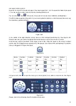
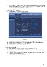
Figure 4-35
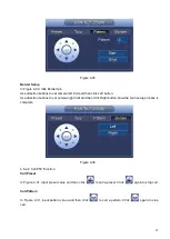
Border Setup
In
Figure 4-32, click Border tab.
Use direction buttons to set camera left limit and then click Left button.
Use direction buttons to set camera right limit and then click Right button. Now the scan setup process is
complete.
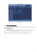
Figure 4-36
4.6.2.2 Call PTZ Function
Call Preset
In Figure 4-31, input preset value and then click
to call a preset. Click
again to stop call.
Call Pattern
In Figure 4-31, input pattern value and then click
to call a pattern. Click
again to stop
call.
Summary of Contents for k-nl304k
Page 1: ...Network Disk Recorder User s Manual Model No K NL304K K NL308K K NL316K Version 1 0 5 ...
Page 32: ...23 The following figure is based on our K NL316K product Figure 3 2 ...
Page 50: ...41 Figure 4 25 ...
Page 67: ...58 Figure 4 52 Figure 4 53 ...
Page 88: ...79 Figure 4 71 Figure 4 72 ...
Page 89: ...80 Figure 4 73 Figure 4 74 ...
Page 94: ...85 Figure 4 78 Figure 4 79 ...
Page 95: ...86 Figure 4 80 Figure 4 81 ...
Page 96: ...87 Figure 4 82 Figure 4 83 ...
Page 99: ...90 Figure 4 86 Figure 4 87 ...
Page 114: ...105 send rate and receive rate at the top panel Figure 4 105 ...
Page 119: ...110 Figure 4 111 Figure 4 112 ...
Page 129: ...120 Figure 4 125 Figure 4 126 ...
Page 164: ...155 Figure 5 38 Figure 5 39 Figure 5 40 ...
Page 172: ...163 Figure 5 51 Figure 5 52 Figure 5 53 Figure 5 54 ...

