background image

3

2 Device Installation 

Important

• Make sure that the installation area is strong enough to hold the product, such as a

concrete ceiling.

• Install the camera in the foundation area of the architecture or where sufficient strength

is assured.

• If a wall or ceiling board such as plasterboard is too weak to support the total weight, the 

area shall be sufficiently reinforced.

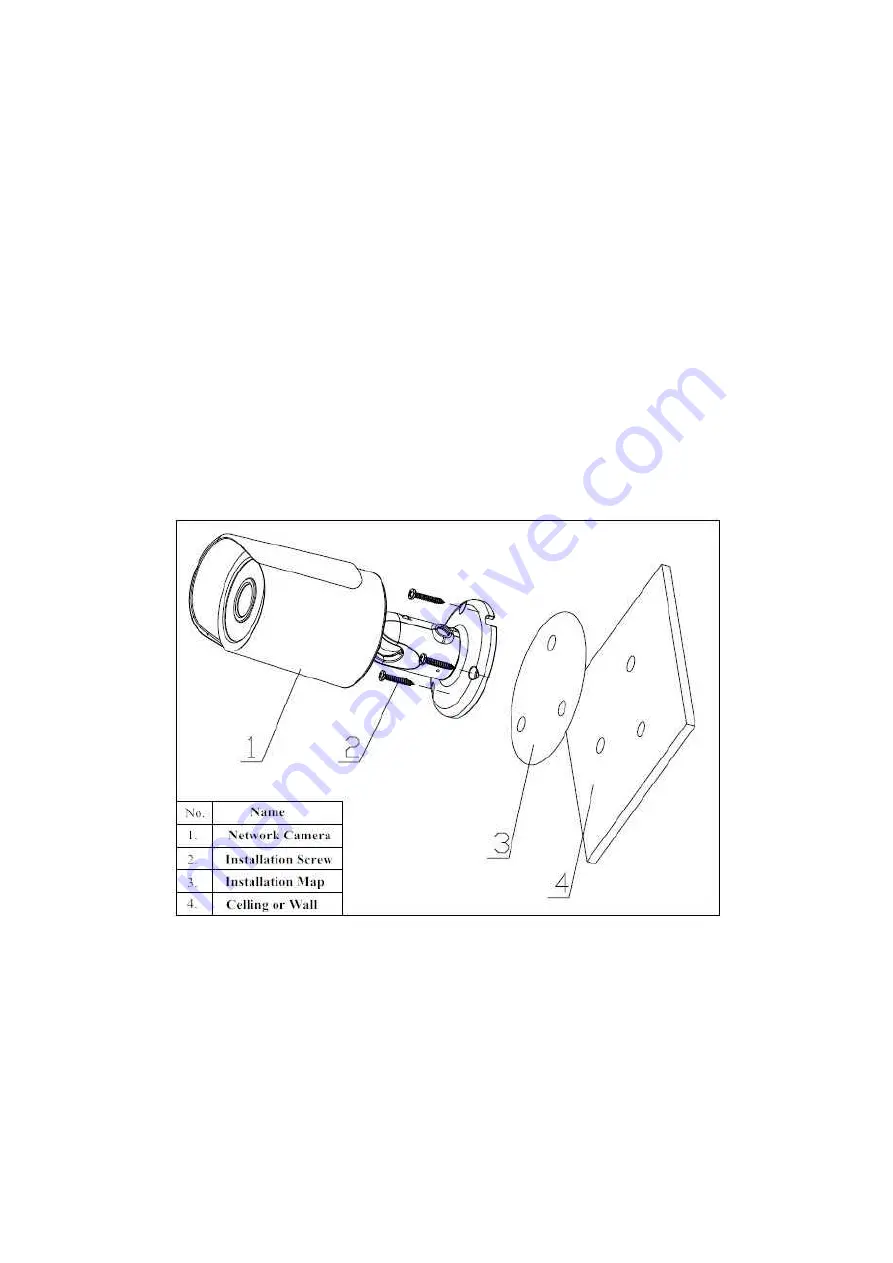
Please see Figure 2-1 and Figure 2-2.

Step 1

Stick installation sticker to designated surface where you will install the device (wall or ceiling).

Step 2

Affix the installation template label (accessory) to the ceiling or wall, and use a pen to mark the

positions of the screws and cable mounting hole in the ceiling or wall. Remove the installation

template label and attach the camera with 3 screws (locally procured).

Step 3

Plug external wiring of the device properly.

Figure 2-1 Device installation 1

Step 4

Use Philip’s head screw (in accessories bag) to loosen adjusting screw.

Step 5

Adjust the device in all possible directions, and set its monitoring direction.

Step 6

Use Philip’s head screw to tighten the screws

Summary of Contents for K-EW114L03E

Page 1: ...HD IR Waterproof Fixed Network Camera Quick Start Guide Model No K EW114L03E K EW114L06E K EW114L08E Version 1 0 0...

Page 2: ...We are not liable for any problems caused by unauthorized modification or attempted repair 2 Transportation security Heavy stress violent vibration or water splash are not allowed during transportati...

Page 3: ...use the camera Dome enclosure is the optical component do not touch the enclosure when you are installing the device or clean the enclosure when you are doing maintenance work Please use professional...

Page 4: ...1 1 1 Multiple function Combination Cable 1 1 2 Framework and Dimension 2 2 Device Installation 3 3 Quick Configuration Tool 5 3 1 Overview 5 3 2 Operation 5 4 Web Operation 7 4 1 Network Connection...

Page 5: ...on combination cable information See Figure 1 1 Figure 1 1 Multiple function combination cable Please refer to the following sheet for detailed information No Port Name Function Connection Note 1 LAN...

Page 6: ...ramework and Dimension Please refer to the following two figures for dimension information The unit is mm See Figure 1 2 and Figure 1 3 Figure 1 2 Dimension illustration 1 Figure 1 3 Dimension illustr...

Page 7: ...to designated surface where you will install the device wall or ceiling Step 2 Affix the installation template label accessory to the ceiling or wall and use a pen to mark the positions of the screws...

Page 8: ...4 Figure 2 2 Device installation 2...

Page 9: ...n Double click the ConfigTools exe icon you can see an interface is shown as in Figure 3 1 In the device list interface you can view device IP address port number subnet mask default gateway MAC addre...

Page 10: ...user name password and port Please modify the corresponding information to login Please note the port information here shall be identical with the port value you set in TCP port in Web Network interfa...

Page 11: ...nd gateway of the PC and the network camera respectively Network camera default IP address is 192 168 0 10 Subnet mask is 255 255 255 0 Gateway is 192 168 0 1 z Use order ping network camera address t...

Page 12: ...e the main window Please refer to the Web Operation Manual included in the resource CD for detailed operation instruction Note z This quick start guide is for reference only Slight difference may be f...

Reviews: