background image

ii

6. Daily Maintenance

Please shut down the device and then unplug the power cable before you begin daily maintenance 

work. 

Do not touch the CCD (CMOS) optic component. You can use the blower to clean the dust on the lens 

surface.

Always use the dry soft cloth to clean the device.  If there is too much dust, please use the water to 

dilute the mild detergent first and then use it to clean the device. Finally use the dry cloth to clean the 

device.

Please put the dustproof cap to protect the CCD (CMOS) component when you do not use the camera.

Dome enclosure is the optical component, do not touch the enclosure when you are installing the 

device or clean the enclosure when you are doing maintenance work. Please use professional optical 

clean method to clean the enclosure. Improper enclosure clean method (such as use cloth) may result 

in poor IR effect of camera with IR function.  

7. Accessories

Be sure to use all the accessories recommended by manufacturer.

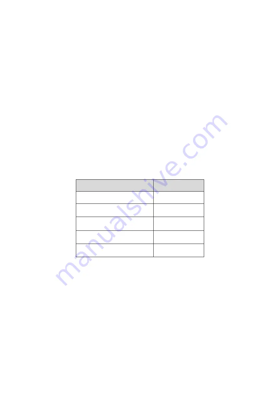
Before installation, please open the package and check all the components are included.

Contact your local retailer ASAP if something is broken in your package.

Accessory Name

Amount

Network Camera Unit

1

Quick Start Guide

1

Installation Accessories Bag

1

CD

1

Important Safety Instructions

1

Summary of Contents for K-EW114L03E

Page 1: ...HD IR Waterproof Fixed Network Camera Quick Start Guide Model No K EW114L03E K EW114L06E K EW114L08E Version 1 0 0...

Page 2: ...We are not liable for any problems caused by unauthorized modification or attempted repair 2 Transportation security Heavy stress violent vibration or water splash are not allowed during transportati...

Page 3: ...use the camera Dome enclosure is the optical component do not touch the enclosure when you are installing the device or clean the enclosure when you are doing maintenance work Please use professional...

Page 4: ...1 1 1 Multiple function Combination Cable 1 1 2 Framework and Dimension 2 2 Device Installation 3 3 Quick Configuration Tool 5 3 1 Overview 5 3 2 Operation 5 4 Web Operation 7 4 1 Network Connection...

Page 5: ...on combination cable information See Figure 1 1 Figure 1 1 Multiple function combination cable Please refer to the following sheet for detailed information No Port Name Function Connection Note 1 LAN...

Page 6: ...ramework and Dimension Please refer to the following two figures for dimension information The unit is mm See Figure 1 2 and Figure 1 3 Figure 1 2 Dimension illustration 1 Figure 1 3 Dimension illustr...

Page 7: ...to designated surface where you will install the device wall or ceiling Step 2 Affix the installation template label accessory to the ceiling or wall and use a pen to mark the positions of the screws...

Page 8: ...4 Figure 2 2 Device installation 2...

Page 9: ...n Double click the ConfigTools exe icon you can see an interface is shown as in Figure 3 1 In the device list interface you can view device IP address port number subnet mask default gateway MAC addre...

Page 10: ...user name password and port Please modify the corresponding information to login Please note the port information here shall be identical with the port value you set in TCP port in Web Network interfa...

Page 11: ...nd gateway of the PC and the network camera respectively Network camera default IP address is 192 168 0 10 Subnet mask is 255 255 255 0 Gateway is 192 168 0 1 z Use order ping network camera address t...

Page 12: ...e the main window Please refer to the Web Operation Manual included in the resource CD for detailed operation instruction Note z This quick start guide is for reference only Slight difference may be f...

Reviews: