25
8.3.
Disassembly Procedure for the
Unit
No.
Item
Fig
Removal
1
Side Case-L Unit
2 Screws (A)
1 Screws (B)
2 Screws (C)
3 Screws (D)
1 Locking tab
4 Hanging parts
P6005 (Connector)
Side Case-L Unit
2
Top Case Unit
1 Screw (E)
1 Screw (F)
5 Locking tabs
FP6402 (Flex)
P6401 (Connector)
Top Case Unit
3
ESD P.C.B.
(HDC-TM90/TM99
only)
2 Screws (G)
FP3201 (Flex)
ESD P.C.B.
4
Front Case Unit
1 Screw (H)
2 Screws (I)
P7001(Connector)
P7002 (Connector)
2 Locking tabs
1 Rib
FP6003 (Flex)
Front Case Unit
5
Lens Frame Unit
4 Screws (J)
2 Locking tabs
FP6004 (Flex)
FP6005 (Flex)
Lens Frame Unit
6
Lens Unit
FP6008 (Flex)
P6001 (Connector)
Lens Unit
NOTE: (When Installing)
7
Main P.C.B.
SD Holder P.C.B.
1 Screw (K)
Battery Frame
2 Screws (L)
FP6001 (Flex)
P6003 (Connector)
SD Holder P.C.B.
Main P.C.B.
NOTE: (When Installing)
8
Battery P.C.B.
Battery P.C.B.
9
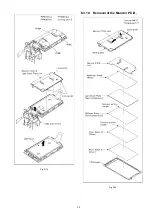
Monitor P.C.B. &
Light Guide Plate Unit
LCD Unit
2 Screws (N)
6 Locking tabs
LCD Case (T) Unit
2 Screws (O)
3 Ribs
LCD Frame
FP901 (Flex)
FP904 (Flex)
FP905 (Flex)
3 Locking tabs
Monitor P.C.B. &
Light Guide Plate Unit
LCD Unit
10
Monitor P.C.B.
1 Locking tab
1 Hanging part
Reflection Sheet
Light Guide Plate
Diffusion Sheet
Prism Sheet B
Prism Sheet A
LCD Holder
11
MOS Unit
IR Filter
3 Screws (P)
MOS Cushion
MOS Unit
IR Filter
12
2nd Lens Frame
Stepping Motor
4th Lens Frame
Stepping Motor
3 Screws (Q)
Solder (4 points)
2 Projection Part
2nd Lens Frame Stepping
Motor
2 Screws (R)
Solder (6 points)
2 Projection Part
4th Lens Frame Stepping
Motor
No.
Item
Fig
Removal
Summary of Contents for HDC-SD90EB
Page 10: ...10 3 5 Formatting ...
Page 11: ...11 4 Specifications ...
Page 12: ...12 ...
Page 26: ...26 8 3 1 Removal of the Side Case L Unit Fig D1 Fig D2 ...
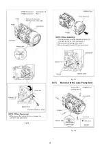
Page 28: ...28 Fig D6 Fig D7 8 3 5 Removal of the Lens Frame Unit Fig D8 ...
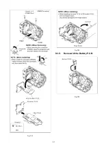
Page 29: ...29 Fig D9 8 3 6 Removal of the Lens Unit Fig D10 ...
Page 30: ...30 Fig D11 8 3 7 Removal of the Main P C B and SD Holder P C B Fig D12 ...
Page 31: ...31 Fig D13 Fig D14 8 3 8 Removal of the Battery P C B Fig D15 ...
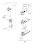
Page 32: ...32 8 3 9 Removal of the Monitor P C B Light Guide Plate Unit and LCD Unit Fig D16 Fig D17 ...
Page 33: ...33 Fig D18 8 3 10 Removal of the Monitor P C B Fig D19 ...
Page 35: ...35 Fig D22 ...
Page 56: ...S7 Exploded View S7 1 Frame and Casing Section 1 S 17 B3 12 B13 11 B4 B5 B6 B7 8 ...
Page 58: ...S 19 S7 3 LCD Section 28 24 25 26 21 22 23 7 20 29 B24 B23 B26 B25 16 27 ...


