20
6.5.
Erasing the lock histories
Touch the [ 10 ] of LCD, select erasing the lock histories execution.
Operation specifications
Indication contents
• Erasing the error histories stored in EEPROM. (working time is not erased)
Press the power button and turn off.
6.6.
Erasing the internal media management information
(HDC-TM90/TM99 only)
Touch the [ 11 ] of LCD, select erasing the internal media management information for fast boot stored in flash memory.
Operation specifications
Indication contents
• The fast boot management informations of the internal media are stored in the flash memory.
The following cases, be sure to implement for protection of customer's recorded data.
However, if there is no problem to delete customer's recorded data, erasing the internal media management information is not
required.
• Case1:
When replacing the flash memory chip (IC3402) or replacing the MAIN P.C.B. Unit.
Before checking the operations after replacing the parts, erasing the internal media management information.
• Case2:
When replacing the ESD P.C.B. Unit.
Before replacing the ESD P.C.B. Unit, erasing the internal media management information. then replace it new one.
CAUTION:
When turning the unit on after performing the above operation, the internal media management information is stored into the unit,
the playback of the recorded data is normally.
When not performing the above operation, the customer's recorded data will disappear.
Press the power button and turn off.
Summary of Contents for HDC-SD90EB
Page 10: ...10 3 5 Formatting ...
Page 11: ...11 4 Specifications ...
Page 12: ...12 ...
Page 26: ...26 8 3 1 Removal of the Side Case L Unit Fig D1 Fig D2 ...
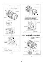
Page 28: ...28 Fig D6 Fig D7 8 3 5 Removal of the Lens Frame Unit Fig D8 ...
Page 29: ...29 Fig D9 8 3 6 Removal of the Lens Unit Fig D10 ...
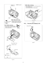
Page 30: ...30 Fig D11 8 3 7 Removal of the Main P C B and SD Holder P C B Fig D12 ...
Page 31: ...31 Fig D13 Fig D14 8 3 8 Removal of the Battery P C B Fig D15 ...
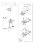
Page 32: ...32 8 3 9 Removal of the Monitor P C B Light Guide Plate Unit and LCD Unit Fig D16 Fig D17 ...
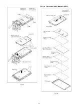
Page 33: ...33 Fig D18 8 3 10 Removal of the Monitor P C B Fig D19 ...
Page 35: ...35 Fig D22 ...
Page 56: ...S7 Exploded View S7 1 Frame and Casing Section 1 S 17 B3 12 B13 11 B4 B5 B6 B7 8 ...
Page 58: ...S 19 S7 3 LCD Section 28 24 25 26 21 22 23 7 20 29 B24 B23 B26 B25 16 27 ...


