27
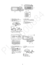
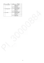
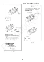
16 2nd Stepping Motor
(Fig. D25) Solder x 16 points
Screw (W) x 3
Convex x 5
(Fig. D26) Screw (X) x 2
2nd Stepping Motor
17 3rd Stepping Motor
(Fig. D27) Solder x 4 points
Screw (Y) x 1
Convex x 1
(Fig. D28) Screw (Z) x 2
3rd Stepping Motor
18 Focus Motor
(Fig. D29) Solder x 8 points
Screw (a) x 1
Convex x 1
(Fig. D30) Screw (b) x 2
Focus Motor
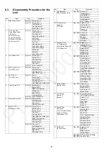
No.
Item
Fig
Removal
Summary of Contents for HC-V270PP
Page 12: ...12 ...
Page 14: ...14 ...
Page 15: ...15 ...
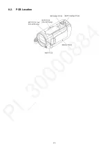
Page 25: ...25 8 2 PCB Location ...
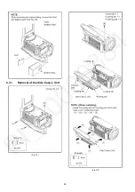
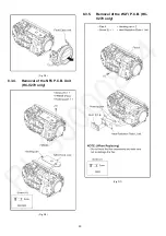
Page 28: ...28 8 3 1 Removal of the Side Case L Unit Fig D1 Fig D2 ...
Page 31: ...31 8 3 6 Removal of the Lens Frame Unit Fig D8 Fig D9 ...
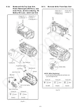
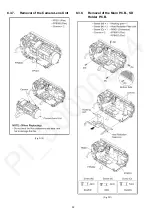
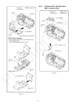
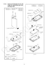
Page 33: ...33 Fig D12 8 3 9 Removal of the Top Operation BATT Catcher P C B Fig D13 ...
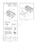
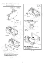
Page 34: ...34 8 3 10 Removal of the R Frame Unit Speaker LCD Unit Fig D14 Fig D15 ...
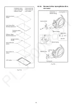
Page 36: ...36 Fig D18 8 3 12 Removal of the Spring Holder Bar rier Lever Fig D19 ...
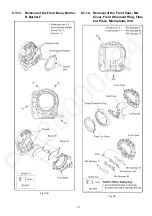
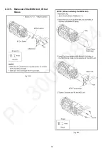
Page 38: ...38 8 3 15 Removal of the MOS Unit IR Cut Grass Fig D22 Fig D23 ...
Page 39: ...39 Fig D24 8 3 16 Removal of the 2nd Stepping Motor Fig D25 ...
Page 40: ...40 Fig D26 8 3 17 Removal of the 3rd Stepping Motor Fig D27 ...
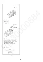
Page 41: ...41 Fig D28 8 3 18 Removal of the Focus Motor Fig D29 ...
Page 42: ...42 Fig D30 ...
Page 46: ...46 9 1 2 Adjustment Items Adjustment item as follows ...
Page 49: ...49 ...
Page 50: ...50 ...
Page 51: ...51 ...
Page 52: ...52 ...
Page 53: ...53 ...
Page 54: ...54 ...


