16
Part Names and Functions
2
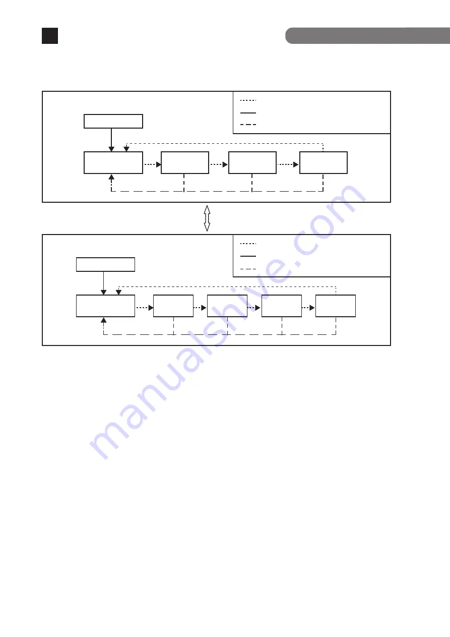
Switch two types of Base modes and their LEDs in the following way:
When Base mode is Status mode (factory default setting)
When Base mode is ECO mode
Switch Base mode (keep pressing "LED DISPLAY
CHANGE BUTTON" over 3 seconds)
Press "LED DISPLAY CHANGE BUTTON" manually.
Automatic
Automatically returns to Base mode after 1 minute.
●
Loop detection/shutoff function and loop history function
If you wish to clear loop detection history, turn OFF once the power supply of the
Ethernet Switch and turn it ON again.
Then, loop detection history is deleted.
The Ethernet Switch can hold up to 64 loop history logs.
Boot
Status mode
(Base mode)
GIGA mode
DUPLEX
mode
Loop History
mode
Press "LED DISPLAY CHANGE BUTTON" manually.
Automatic
Automatically returns to Base mode after 1 minute.
Boot
ECO mode
(Base mode)
Status
mode
GIGA
mode
DUPLEX
mode
Loop history
mode
※
The Base mode is maintained even after the power is turned OFF.
LED lamps for each mode and LED lamps for ports 1 to 20 correspond as shown in Table 1 (see page 14).
Turns on the port LED with a orange light when a loop occurs in the corresponding port.
The Loop shutoff mode has the following 2 types of modes.
- Block mode (factory default)
When loops are detected, the port statuses are automatically blocked, and just the specified
packets which include the loop detection packets will be transmitted and received.
- Shut-down mode
When loops are being detected, the ports will be automatically linked down, and none of
the packets will be transmitted and received.
*Just the loop detection packets from 30 seconds before the set restoration times will
automatically be transmitted and received.
During loop is occurring, or if loop has occurred within the latest 3 days, LOOP HISTORY
LED blinks to notify this. It is possible to switch loop detection setting (OFF/ON) by using a
console cable (for details, see the PDF version of the Operating Instructions). The default
setting is ON.
CONSOLE
9600.N.8.1(DTE)
SFP▲(19)
SFP▼(20)
SFP▲(17)
SFP▼(18)
LEFT LED(ORANGE):LOOP DETECTION
1
2
3
4
5
6
7
8
9
10
11
12
13
14
15
16
17
18
19
20
Ports 1 to 16 support IEEE802.3at/af PoE. This function allows for power supply of up to 30 W through
each port and 250W in total through the Ethernet switch.
PoE power supply function operation overview
2.2 PoE power supply function
Port LEDs (right) 1 to 16
Green Light: Supplying power normally.
Orange Blink: Overload caused by a single port. (Requested power is exceeding 30 W. *1) or
total power supplied by the Ethernet switch.
Off: Not supplying power or no PoE-powered device connected.
PoE LIM. LED (PoE limit)
For silent fan control high-speed (High)* For factory default, or low-speed (Low2)
Off:
Supplying power in the range from 0 to 235 W.
Green Light: Supplying power in the range from 235 to 250 W.
Orange Blink: A single port's power supply is exceeding the upper limit, or the total power
supply of the Ethernet switch is exceeding 250 W.
For silent fan control low-speed (Low1), or min-speed (Min)
Off:
Supplying power in the range from 0 to 170 W.
Green Light: Supplying power in the range from 170 to 185 W.
Orange Blink: A single port's power supply is exceeding the upper limit, or the total power
supply of the Ethernet switch is exceeding 185 W.
*1 When configured IEEE802.3at (factory default). Exceeds 15.4 W when configured IEEE802.3af.
When the requested power supply for the Ethernet switch is exceeded and it gets overloaded, the
power supply to the low priority ports is stopped, and the port LEDs (right) of the ports whose power
supply have been stopped blink orange.
The priority settings for the power supply can be set and changed from the console, etc.
Power supply while the PoE LIM. LED is blinking orange
(overload caused by the total power supplied by the Ethernet switch)
When the power supply which is requested exceeds 30 W via a single port and the port LED (right)
blinks orange, and the power supply is stopped.
Unplug the port cable which is blinking orange, and check the PoE receiving equipment’s specifications.
Caution: 1) Some PoE-powered devices may have a large difference in power consumption between
their maximum power use condition and normal condition. Carefully configure them so
that the upper limit of power supply will not be exceeded.
2) If you do not set a priority for power supply or if the same priority is given, note that the
power supply priority is assigned to the ports in ascending order of the port numbers.
(If the requested power supply for the device overall is exceeded, then the power supply to
a port with a higher port number will be stopped first.)
Power supply while the overload is caused by a single port
* For the configuration and management method, please see the PDF version
Operating Instructions on Panasonic’s website.


