


34
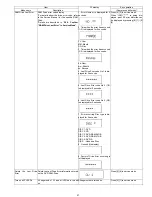
10.8. VTR Mechanism Unit
1. Disconnect 3 Connectors (P1531, P2501 and P4002).
2. Remove 3 Black Screws (A), Screw (B) , Screw (C) and
Screw (D).
3. Lift up VTR Mechanism Unit perpendicularly so to discon-
nect Connectors (P2571 and P3001).
Note:
Pay attention to stiff connections of P2571 and P3001,
when removing VTR Mechanism Unit.
10.8.1.
Caution for attaching VTR Mecha-
nism Unit
1. Because Position SW should be set to "Eject Position",
refer to fig.(A) and set the position switch so that the boss
and arrow mark come on a straight line.
1.Attach VTR Mechanism Unit so that Boss of Position SW
is put into long hole of Main Cam Gear, refer to Fig. (B).
Summary of Contents for DMR-ES40VP
Page 9: ...9 4 Specifications ...
Page 11: ...11 6 Location of Controls and Components 6 1 Each Buttons ...
Page 12: ...12 ...
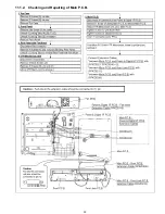
Page 39: ...39 11 1 2 Checking and Repairing of Main P C B ...
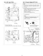
Page 40: ...40 11 1 3 Checking and Repairing of Digital P C B ...
Page 41: ...41 11 1 4 Checking and DVD RAM Drive ...
Page 102: ...S 51 ...
Page 111: ...S 60 ...
Page 112: ...S 61 ...
Page 113: ...S 62 ...
Page 114: ...S 63 ...
Page 115: ...S 64 ...
Page 116: ...S 65 ...
Page 117: ...S 66 ...
Page 119: ...S 68 ...


