background image

6

2.3.

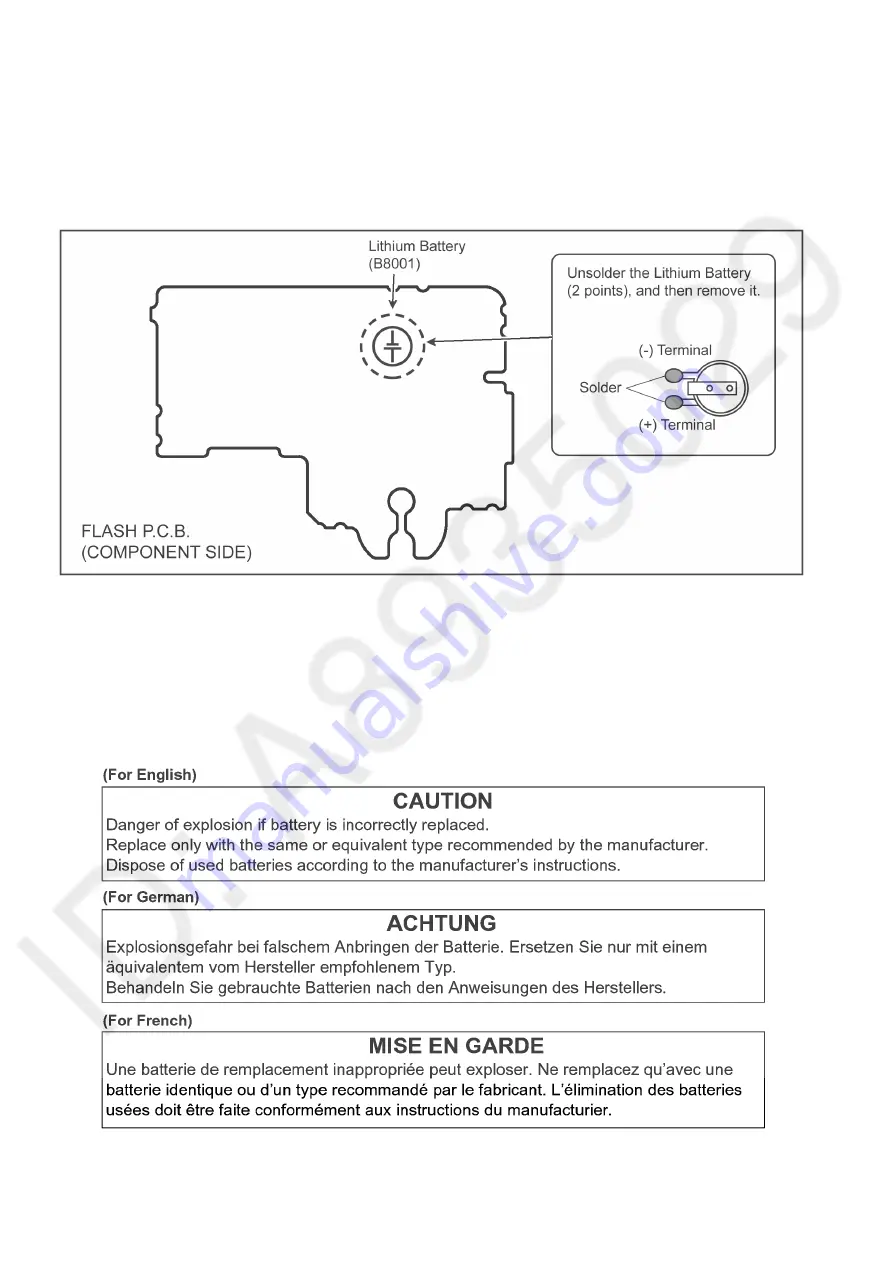
How to Replace the Lithium Battery

2.3.1.

Replacement Procedure

1. Remove the Flash P.C.B.. (Refer to Disassembly Procedures.)
2. Unsolder the each soldering point of electric lead terminal for Lithium battery (Ref. No. "B8001" at component side of Flash 

P.C.B.) and remove the Lithium battery together with electric lead terminal. Then replace it into new one.

NOTE:

The Lithium battery includes electric lead terminals.

NOTE:

This Lithium battery is a critical component. 
It must never be subjected to excessive heat or discharge.
It must therefore only be fitted in requirement designed specifically for its use.
Replacement batteries must be of same type and manufacture.
They must be fitted in the same manner and location as the original battery, with the correct polarity contacts observed.
Do not attempt to re-charge the old battery or re-use it for any other purpose.
It should be disposed of in waste products destined for burial rather than incineration.

NOTE:

Above caution is applicable for a battery pack which is for DMC-FZ300/FZ330 series, as well.

Summary of Contents for DMC-FZ300PP

Page 1: ...ion is a violation of law ORDER NO DSC1509019CE B26 Digital Camera Model No DMC FZ300PP DMC FZ300EE DMC FZ300EF DMC FZ300EG DMC FZ300EP DMC FZ300GA DMC FZ300GC DMC FZ300GD DMC FZ300GH DMC FZ300GK DMC FZ300GN DMC FZ300GT DMC FZ300SG DMC FZ330EB Colour K Black Type ...

Page 2: ...C B Unit 24 8 Service Fixture Tools 25 8 1 Service Fixture and Tools 25 8 2 When Replacing the Main P C B 26 8 3 Service Position 26 9 Disassembly and Assembly Instructions 27 9 1 Disassembly Flow Chart 27 9 2 P C B Location 27 9 3 Disassembly Procedure 28 9 4 Lens Disassembly Procedure 42 9 5 Removal of the MOS Unit 50 9 6 Main exterior parts assembly procedure 51 10 Measurements and Adjustments ...

Page 3: ...xposed to shock hazards 1 2 Leakage Current Cold Check 1 Unplug the AC cord and connect a jumper between the two prongs on the plug 2 Measure the resistance value with an ohmmeter between the jumpered AC plug and each exposed metallic cabinet part on the equipment such as screwheads connectors control shafts etc When the exposed metallic part has a return path to the chassis the reading should be ...

Page 4: ...cuit on Flash P C B Unit when servicing Discharging Procedure 1 Put the insulation tube on the lead part of resistor ERG5SJ102 1k 5W An equivalent type of resistor may be used 2 Put the resistor between both terminals of E Capacitor on the Flash P C B Unit for approx 5 seconds 3 After discharging confirm that the E Capacitor voltage is lower than 10V by using a voltmeter Fig F1 ...

Page 5: ...ices 4 Use only an antistatic solder removal device Some solder removal devices not classified as antistatic ESD protected can generate electrical charge sufficient to damage ES devices 5 Do not use freon propelled chemicals These can generate electrical charges sufficient to damage ES devices 6 Do not remove a replacement ES device from its protective package until immediately before you are read...

Page 6: ...Lithium battery is a critical component It must never be subjected to excessive heat or discharge It must therefore only be fitted in requirement designed specifically for its use Replacement batteries must be of same type and manufacture They must be fitted in the same manner and location as the original battery with the correct polarity contacts observed Do not attempt to re charge the old batte...

Page 7: ...ug must not be used until a replacement cover is obtained A replacement fuse cover can be purchased from your local Panasonic Dealer If the fitted moulded plug is unsuitable for the socket outlet in your home then the fuse should be removed and the plug cut off and disposed of safety There is a danger of severe electrical shock if the cut off plug is inserted into any 13 ampere socket If a new plu...

Page 8: ...S Unit fixing screws are loosened the Optical tilt adjustment must be performed About the Optical tilt adjustment refer to the 10 3 2 Adjustment Specifications for details 3 2 2 About Venus Engine IC6001 Located on the Main P C B The Venus Engine IC6001 consists of two IC chips DRAM and Venus which are fixed together with solder It s called Package On Package type IC When replacing always replace ...

Page 9: ...ation 1 Movement of Weight is detected by capacitance A 2 Each acceleration of the X Y Z axis is converted into data and they are output 3 The VENUS ENGINE converts the data into a horizontal angle and an angle of inclination and displays them to screen 3 3 2 About Wi Fi Function The page number in this chapter does not show the page number of this service manual ...

Page 10: ...nnection the customer has registered For the protection of private information please erase the personal information after the completion of repair by Initial Settings In addition please print out the following documents and pass to the customer with the camera unit Printing Material Leaflet for Customer ...

Page 11: ...g the equipment for which the lead free solder is used Definition The letter of PbF is printed on the P C B using the lead free solder To put lead free solder it should be well molten and mixed with the original lead free solder Remove the remaining lead free solder on the P C B cleanly for soldering of the new IC Since the melting point of the lead free solder is higher than that of the normal le...

Page 12: ...30EB d DMC FZ300EE e DMC FZ300GN f DMC FZ300GT g DMC FZ300GK h DMC FZ300GD i DMC FZ300GA GC GH What is the difference is that the Initial Settings data which is stored in Flash ROM mounted on Main P C B 3 5 1 Defining methods To define the model suffix to be serviced refer to the nameplate which is putted on the bottom side of the unit NOTE After replacing the Main P C B be sure to achieve adjustm...

Page 13: ...charged Battery and insert the memory card 32MB or more Remove the lens cap Step 1 The Temporary Cancellation of Initial Settings Set the Mode dial to P Program AE mode While pressing DISP button RIGHT of Cursor buttons and AF AE LOCK button simultaneously turn the power on Step 2 The Cancellation of Initial Settings Press the Playback button in order to enter the Playback mode Press AF AE LOCK bu...

Page 14: ...s Three pages in total Only DMC FZ300EF EG EP and FZ330 models SEP0514AB is used as a Main P C B When Main P C B has just been replaced only 5 model suffixes are displayed as follows Two page 5 in total CASE 2 Other than After replacing Main P C B and or Flash ROM Step 5 Choose the model suffix in Initial Settings Refer to CAUTION Caution After replacing Main P C B and or Flash ROM The model suffi...

Page 15: ...nitial Settings MODEL VIDEO OUTPUT LANGUAGE DATE REMARKS a DMC FZ300 Japan domestic model NTSC Japanese Year Month Date b DMC FZ300PP NTSC English Month Date Year c DMC FZ300EE PAL Russian Date Month Year d DMC FZ300EF PAL English Date Month Year e DMC FZ300EG PAL English Date Month Year f DMC FZ300EP PAL English Date Month Year g DMC FZ300GA PAL English Date Month Year h DMC FZ300GC PAL English D...

Page 16: ...16 4 Specifications The following specification is for DMC FZ300PP Some specifications may differ depending on model suffix ...

Page 17: ...17 ...

Page 18: ...18 ...

Page 19: ...n of Controls and Components The following description is for DMC FZ300PP Some descriptions may differ depending on model suffix The page number in this chapter does not show the page number of this service manual ...

Page 20: ...20 ...

Page 21: ... display The error code can be displayed by ordering the following procedure Preparation Attach the fully charged Battery and insert the memory card 32MB or more Remove the lens cap Step 1 The Temporary Cancellation of Initial Settings Set the Mode dial to P Program AE mode While pressing DISP button RIGHT of Cursor buttons and AF AE LOCK button simultaneously turn the power on Step 2 Execute the ...

Page 22: ...echanical lock FP9005 4 15 signal line or IC6001 VENUS ENGINE 0 50 Zoom motor sensor error During monitor mode with slow speed Mechanical lock FP9005 4 15 signal line or IC6001 VENUS ENGINE 0 60 Detection of zoom misregistration by impact such as fails No indication No indication Lens Unit OIS 1000 PSD X error Hall element X axis position detect error in OIS unit OIS X LENSu NG OIS Unit 2000 PSD Y...

Page 23: ...error 9000 OIS adj Pitch direction off set error A000 OIS adj Yaw direction gain error B000 OIS adj Pitch direction gain error C000 OIS adj Yaw direction position sensor error D000 OIS adj Pitch direction position sensor error E000 OIS adj other error HARD FLASH Flash 28 0 0000 Flash charging capacitor did not been fully charged within 20 seconds STRB CHG FLASH P C B FPC FLASH ROM Data Area 2B 0 0...

Page 24: ...customer run the Reset Wi Fi Settings for removing Wi Fi password then check the operation Reset Procedure of Wi Fi Settings 1 Press the MENU SET button and select the SETUP mode by Cursor buttons then press the MENU SET button 2 Select Reset Wi Fi Settings by Cursor buttons then press the MENU SET button 3 Select YES and press the MENU SET button The Reset Wi Fi Settings performs not only resetti...

Page 25: ...25 8 Service Fixture Tools 8 1 Service Fixture and Tools The following Service Fixture and tools are used for checking and servicing this unit ...

Page 26: ...oon even if the AC Cord is unplugged or the battery is removed 2 Be careful of the high voltage circuit on Flash P C B Unit 3 DO NOT allow other parts to touch the high voltage circuit on Flash P C B Unit No Parts No Connection Form 1 VFK1870 PS9001 MAIN PP8001 FLASH 30pin B to B 2 VFK2024 FP9005 MAIN LENS UNIT 51pin 0 3 FFC 3 RFKZ0392 FP9007 MAIN REAR OPERATION UNIT 14pin 0 5 FFC 4 RFKZ0626 FP900...

Page 27: ...27 9 Disassembly and Assembly Instructions 9 1 Disassembly Flow Chart This is a disassembling chart When assembling perform this chart conversely 9 2 P C B Location ...

Page 28: ...x 4 Side Operation Unit Front Case Unit 7 Battery Door Unit Fig D16 Screw Q 2 Battery Door Unit 8 Flash P C B Unit Fig D17 Convex 1 Locking tab 1 Fig D18 Screw R 1 Locking tab A 3 Condenser Cover Locking tab B 2 Fig D19 Solder 4 points Flash P C B Unit 9 LVF Module Fig D20 Convex A 2 Hooking part A 2 Multi FPC Unit Screw S 2 Convex B 2 Locking tab 2 Hooking part B 2 LVF Cover Unit LVF Unit Heat Ra...

Page 29: ...29 9 3 1 Removal of the Rear Case Unit Fig D1 Fig D2 ...

Page 30: ...30 Fig D3 Fig D4 ...

Page 31: ...31 Fig D5 9 3 2 Removal of the Main P C B Fig D6 ...

Page 32: ...32 Fig D7 9 3 3 Removal of the Top Case Unit and Battery Case Unit Fig D8 ...

Page 33: ...33 Fig D9 Fig D10 ...

Page 34: ...34 Fig D11 Fig D12 ...

Page 35: ...35 9 3 4 Removal of the Lens Unit Fig D13 9 3 5 Removal of the Mic Jack Holder Mic Jack P C B and Speaker Fig D14 ...

Page 36: ...36 9 3 6 Removal of the Side Operation Unit and Front Case Unit Fig D15 9 3 7 Removal of the Battery Door Unit Fig D16 9 3 8 Removal of the Flash P C B Unit Fig D17 ...

Page 37: ...37 Fig D18 Fig D19 ...

Page 38: ...38 9 3 9 Removal of the LVF Module Fig D20 9 3 10 Removal of the Flash Tray Unit Shoe Spring and Flash Case Top Fig D21 ...

Page 39: ...39 9 3 11 Removal of the Rear Operation Unit and Hinge SW FPC Fig D22 9 3 12 LCD Hinge Unit with LCD Unit Fig D23 ...

Page 40: ...40 9 3 13 Removal of the LCD IF P C B MR Sensor FPC and LCD Unit Fig D24 Fig D25 ...

Page 41: ...ke sure to confirm the following points when installing The screw is tightened enough Installing conditions are fine No distortion no abnormal space No dust and or dirt on lens surfaces LCD image is fine No dust and or dirt on it and no gradient images ...

Page 42: ... axis adjustment finished When remove it refer to item 9 5 2 Keep dust or dirt away from the lens To remove dirt or dust from the lens blow with dry air 3 Do not touch the lens surface 4 Use lens cleaning KIT VFK1900BK 5 Apply grease as shown on item 9 4 8 and 9 4 9 in the figure 9 4 1 Removal of the Lens Flex Unit 1 Unscrew the 2 screws A 2 Remove the 10 Ribs 3 Remove the 3 connector 4 Remove the...

Page 43: ...43 9 4 3 Removal of the Zoom Motor 1 Unscrew the 2 screws C ...

Page 44: ...44 9 4 4 Removal of the 1st Lens Frame Unit 1 Turn the cam frame in the direction of arrow fully and remove the 1st lens frame unit ...

Page 45: ...45 9 4 5 Removal of the 5th Lens Frame Unit 1 Remove the 5th lens frame unit in the direction of arrow ...

Page 46: ... the 2nd Lens Frame Unit 1 Hold the middle frame unit and turn the cam frame unit in the direction of arrow 1 fully about half turn 2 Reverse the cam frame and remove the 2nd lens frame unit Catch the 2nd lens frame unit ...

Page 47: ... Cam Frame Unit 1 Turn the cam frame unit in the direction of arrow 1 fully about half turn 2 Move the 3rd lens frame unit to bottom And turn the cam frame unit in the direction of arrow 2 fully and remove the cam frame unit ...

Page 48: ...48 9 4 8 Removal of the Focus Motor Unit 1 Unscrew the 2 screws D 2 Remove the focus motor unit Also remove the flex from groove ...

Page 49: ...49 9 4 9 Removal of the 4th and 3rd Lens Frame Unit 1 Remove the 4th lens frame unit and 3rd lens frame unit from middle frame unit ...

Page 50: ...the optical tilt adjustment is required When loosen the screw E the optical tilt adjustment is necessary at the end of assembling Refer to item 10 3 2 To prevent the MOS unit from catching the dust and dirt do not remove the MOS unit except replacing it 1 Unscrew the 4 screws E 2 Remove the MOS unit ...

Page 51: ...her sealed When assembling this unit keep the clearance of 0 to 0 2 mm between the Top Case Unit and Rear Grip to maintain its weather sealing performance Procedure Tighten the screws in the order of to For the screws and tighten them while pushing the Top Case Unit ...

Page 52: ...fore Disassembling the unit 10 2 1 Initial Setting Release The cameras specification are initially set in accordance with model suffix such as EB EG GN and so on Unless the initial setting is not released an automatic alignment software in the camera is not able to be executed when the alignment is carried out Note The initial setting should be again done after completing the alignment Otherwise t...

Page 53: ...ata as the way of return when trouble occurs before disassembling the unit depending on each case ROM_BACKUP Method of Non PC backup 1 Insert the memory card into the camera 2 Set the camera to Temporary cancellation of the initial settings 3 Select the SETUP menu From the SETUP menu select ROM_BACKUP NOTE This item is not listed on the customer s SETUP menu 4 When this ROM_BACKUP item is selected...

Page 54: ...ze maximum of the diffusing surface of light box some adjustment items need the distance between diffusing surface of light box and camera body becomes several cent meters Before the adjustments remove the front hood of light box following steps below For RFKZ0523 Light Box ...

Page 55: ...ment Flag Setting Reset Not yet adjusted the status flag condition 1 After pressing the DISP button the LCD monitor displays the Flag status screen Refer to Fig 3 2 2 Select item by pressing the Cursor buttons Gray cursor is moved accordingly 3 Press the Delete Cancel Fn3 button NOTE The selected item s flag has been changed from F green to 0 yellow Flag conditions F green means that the alignment...

Page 56: ...y start the adjustment again 3 Do not press any buttons keys until the default menu Refer to Fig 3 5 is displayed on the LCD monitor Otherwise adjustment data may not be stored properly 4 If the adjustment is interrupted accidentally the alignment data may not be properly saved in the Flash ROM Fig 3 5 10 3 1 5 Finalizing the Adjustment 1 Several adjustment flags can be reset F into 0 at the same ...

Page 57: ...ix table shows the relation between the replaced part and the Necessary Adjustment When a part is replaced make sure to perform the necessary adjustment s in the order indicated The table below shows all the information necessary to perform each adjustment ...

Page 58: ...58 ...

Page 59: ...59 ...

Page 60: ...60 ...

Page 61: ...ng the Main P C B Venus Engine is included or Venus Engine After replacing the Main P C B Venus Engine is included or Venus Engine make sure to perform the Initial Settings first then release the Initial Settings in order to proceed the electrical adjustment NOTE 1 If electrical adjustment or data re writing is executed before Initial Settings suffix code list is never displayed and it cannot be c...

Page 62: ...described in 3 5 2 Initial Settings for details IMPORTANT 1 The initial setting should be done again after completing the alignment Otherwise the camera will not work properly Therefore as a warning the camera display a warning symbol on the LCD monitor every time the camera is turned off 2 Confirm that status of all adjustment flag show F Even if one of the adjustment flag shows 0 initial setting...

Page 63: ...LCD Panel with your hand When cleaning the lens use air blower to blow off the dust When cleaning the LCD Panel dampen the lens cleaning paper with lens cleaner and the gently wipe the its surface Note The Lens Cleaning Kit VFK1900BK Only supplied as 10 set Box is available as Service Aid ...

Page 64: ...64 ...

Page 65: ...O AMP SPEAKER CONTROL SPEAKER VIDEO OUT HDMI TERMNINAL IC8001 IGBT DRIVER COLOR LCD PANEL COLOR LVF 3 0 PANEL 3 2 1040K dots 0 39 PANEL 4 3 EQUIVALENT TO 1440k dots REMOTE TERMINAL STEREO MICROPHONE EXT MIC TERMINAL IC5102 BUS SWITCH IC2001 VIDEO DRIVER IC5403 SINGLE COMPARATOR IC5101 BUS SWITCH 25mm 600mm 4 3 x24 ECM L ECM R X9101 32 768KHz NAND FLASH ROM 1G bit IC6003 EXT FLASH OPTION Q8101 QR81...

Page 66: ...17 GPIO157 GPIO133 GPIO129 B15 RIGHT UP DELETE LEFT DOWN MENU SET DISP FP9007 9 REAR LVR AF B14 FP9007 3 7 14 FP9007 8 FP9007 6 FP9007 11 FP9007 5 FP9007 4 FP9007 2 FP9007 1 MF PLAY AF AE LOCK AFS AFF LVF FN4 SW GPIO151 D19 FP9003 4 POWER MODE DIAL Fn2 Fn1 SHUTTER FULL SHUTTER HALF POWER LED POWER LED ON DIAL 1 3 DIAL 1 2 DIAL 1 1 TOP DIAL 3 TOP DIAL 2 TOP DIAL 1 Wi Fi LED ON PW 5 2V PW D3 1V FP90...

Page 67: ... BLOCK SD CORE USB I F PRE PROCESS BLOCK INTERNAL BUS CONTROL CLK72 MCLK FP9001 48 P6501 MEMORY CARD CONNECTOR FCK R27 USB DM USB DP AF16 AG16 LCD GPIO260 GPIO258 GPIO259 S LCD EVF SDO S LCD EVF SCK FP9003 15 FP9003 16 FP9003 18 FP9003 37 FP9003 39 FP9003 35 20 FP9003 28 FP4101 45 FP4103 13 FP4101 30 FP4103 8 FP4101 26 FP4103 30 FP4101 32 FP4101 FP9003 38 31 FP4101 9 FP4101 11 FP4101 41 FP9009 34 ...

Page 68: ...6 PS9001 5 PS9001 10 PS9001 7 PP8001 1 PP8001 8 PP8001 9 PP8001 6 PP8001 5 PP8001 10 PP8001 1 PS9001 12 WiFi CMD SDIO CMD 13 WiFi DA3 SDIO D3 2 4G ANT 14 WiFi DA0 SDIO D0 11 WiFi DA1 SDIO D1 10 WiFi DA2 SDIO D2 15 31 RESET N 29 GPIO52 GPIO53 GPIO57 GPIO54 GPIO55 GPIO56 G WiFi CLK WiFi CMD WiFi DAT3 WiFi DAT0 WiFi DAT1 WiFi DAT2 A8 B8 D9 C8 D8 C9 76 79 GPIO106 WiFi RESET NO GUN DET C13 RL9306 RL930...

Page 69: ...EC1 EB EA STB CHG OUT G GYRO REF 12 PIOUT2 9 PIOUT1 118 MRIN1 119 MRIN2 MROUT1 MROUT2 44 ED2 RL7003 R4 GPIO8 2 PWM IRIS B RL7002 EC2 P1 D14 A15 R1 T4 T3 R3 R2 GPIO132 SHUTTER B N6 PGIO38 P7 116 2 3 1 Q8001 D8002 C8006 LAMP RL8001 TRG IN RL8003 LAMP RL8002 GND RL8004 STB CHG OUT EXT STB ON L INT STB ON L EXT STB OUT EXT STB IN EXT STB DET OIS GYRO CS OIS GYRO SCK OIS GYRO DI OIS GYRO DO STB OPEN DE...

Page 70: ...W 1 VCC 23 CPLUS CP SW 24 CMINUS VREGD VREGD2 29 VREGA 20 GND 0 3V 44 Hx5 47 Lx5 Lx5 43 PGND5 38 Hx6 39 Hx6 HVREG DRIVER VREGD DRIVER HVREG DRIVER VREGD DRIVER HVREG DRIVER VREGD DRIVER HVREG DRIVER VREGD DRIVER HVREG DRIVER VREGD DRIVER HVREG DRIVER 40 Lx6 42 PGND5 46 41 Lx6 VREGD VREGD CH7 STEP UP DC DC Current mode DRIVER 34 PGND7 33 SERIAL I F ON OFF LOGIC 35 61 25 HVREG 2 IC1001 7CH SWITCHING...

Page 71: ...4 VOUT VDD GND CE IC6604 REGULATOR IC6612 POWER STATE TRANSITION CONTROL 3 2 1 4 VOUT VDD GND CE CL6502 PW SD31V 18V IC6606 REGULATOR 2 3 4 1 VOUT VIN GND CE PW DRAM1 8V IC6607 REGULATOR 3 4 1 2 VOUT VIN GND CE PW DRAM1 0V QR6602 PW D3 1V PW D3 1V HIBER CTL2 GPIO37 P6 DIO CKE IN GPIO334 AB16 HIBER CTL3 GPIO34 T6 DIO ISO GPIO333 AA17 QR6502 PW D1 8V Q6503 VDD To P6501 4A 4B B12 SD POWER ON L GPIO10...

Page 72: ...CM GND SHIELD ZENC2_ABS GND SHIELD FBP FMBP FAP FMAP FBN FMBN FHP_VCC FHP_LED ST1 IRIS_AP ST4 IRIS_BN ST3 IRIS_BP SH SHUT_OUT1 SH SHUT_OUT2 X_DRV X_DR Y_DRV Y_DR GND SHIELD Y_HO YVO Y_HO YVO X_HO XVO X_HO XVO FP9005 1 3 5 7 9 11 13 15 17 19 21 23 25 27 29 31 33 35 37 39 41 43 45 47 49 51 2 4 6 8 10 12 14 16 18 20 22 24 26 28 30 32 34 36 38 40 42 44 46 48 50 GND AVDD28 GND DVDD12 GND GND DVDD18 GND...

Page 73: ...t Board Please click the radio button for Diagrams II Parts List on the menu bar in XML Service Manual If you want to print please click the icon button for Print on the icon bar and select the item 16 Exploded View and Replacement Parts List Please click the radio button for Diagrams II Parts List on the menu bar in XML Service Manual If you want to print please click the icon button for Print on...

Reviews: