


55
10.3. Details of Electrical Adjustment
10.3.1. How to execute the Electrical Adjustment
It is not necessary to connect the camera to a PC to perform adjustments.
"Flag reset operation" and "Initial setting operation" are required when carrying out the alignment, follow the procedure below.
10.3.1.1. Startup Electrical Adjustment mode
1. Release the initial settings.
2. Insert a recordable memory card (32MB or more).
(Without a memory card, the automatic adjustment can
not executed.)
3. Procedure to set the camera into adjustment mode:
a. Set the mode dial to "[ P ] (Program AE mode)".
b. Turn the Power on pressing "[ LEFT ] of Cursor
buttons" and [ AF/AF LOCCK ] button simultaneously.
LCD monitor displays "SERVICE MODE". (Refer to
Fig. 3-1)
Fig. 3-1
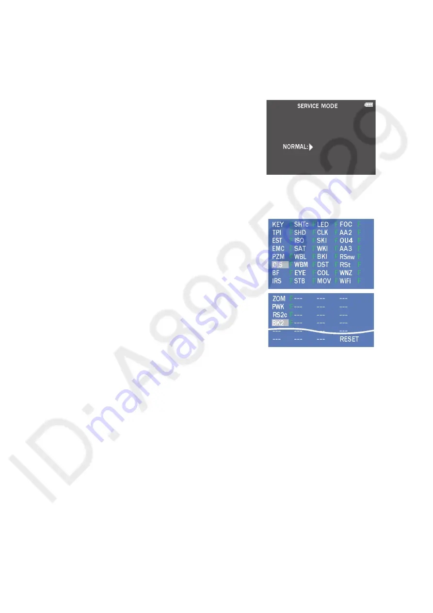
10.3.1.2. Status Adjustment Flag Setting
Reset (Not yet adjusted) the status flag condition.
1. After pressing the [ DISP. ] button, the LCD monitor
displays the Flag status screen. (Refer to Fig.3-2)
2. Select item by pressing the Cursor buttons. (Gray cursor
is moved accordingly.)
3. Press the [ (Delete/Cancel)/Fn3 ] button.
NOTE:
The selected item’s flag has been changed from
"F (green)" to "0 (yellow)".
*Flag conditions:
F (green)
means that the alignment has been completed and the
status flag condition is set. In this case, the flag condition
should be reset, if you try to carry out the automatic
alignment.
0 (yellow)
means that the alignment has been not "completed" and
the status flag condition is "reset". In this case, automatic
alignment is available.
Fig. 3-2
• To display the "BK2" flag, choose the "WiFi" and press the "[ DOWN ] of Cursor buttons".
• In case of setting the status flag into set condition again without completion of the alignment, the status flag should be UNDO by
using ROM BACKUP function.
Summary of Contents for DMC-FZ300PP
Page 17: ...17 ...
Page 18: ...18 ...
Page 20: ...20 ...
Page 29: ...29 9 3 1 Removal of the Rear Case Unit Fig D1 Fig D2 ...
Page 30: ...30 Fig D3 Fig D4 ...
Page 31: ...31 Fig D5 9 3 2 Removal of the Main P C B Fig D6 ...
Page 32: ...32 Fig D7 9 3 3 Removal of the Top Case Unit and Battery Case Unit Fig D8 ...
Page 33: ...33 Fig D9 Fig D10 ...
Page 34: ...34 Fig D11 Fig D12 ...
Page 37: ...37 Fig D18 Fig D19 ...
Page 40: ...40 9 3 13 Removal of the LCD IF P C B MR Sensor FPC and LCD Unit Fig D24 Fig D25 ...
Page 43: ...43 9 4 3 Removal of the Zoom Motor 1 Unscrew the 2 screws C ...
Page 58: ...58 ...
Page 59: ...59 ...
Page 60: ...60 ...
Page 64: ...64 ...


