background image

96

FX-301

Make sure that the power supply is off while cascading or removing the amplifier.

Make sure to check the allowable ambient temperature, as it
depends on the number of amplifiers connected in cascade.

In case two, or more, amplifiers are connected in cascade,
make sure to mount them on a DIN rail.

When connecting in cascade, mount the amplifiers close to each other, fitting
them between the optional end plates (

MS-DIN-E

) mounted at the two ends.

When the amplifiers move on the DIN rail depending on
the attaching condition, fitting them between the optional
end plates (

MS-DIN-E

) mounted at the two ends.

Up to maximum 15 amplifiers can be added (total 16
amplifiers connected in cascade.)

When connecting more than two amplifiers in cascade,

use the sub cable (

CN-71-C

) as the quick-connection

cable for the second amplifier onwards.

Between the 

FX-301B

(

P

)

/G

(

P

)

/H

(

P

) and the 

FX-301

(

P

),

the setting status copy function via communication signal
cannot be used. If coupling these, please arrange
identical models one at a time.

PRECAUTIONS FOR PROPER USE

This product is not a safety sensor. Its use is not
intended or designed to protect life and prevent body
injury or property damage from dangerous parts of
machinery. It is a normal object detection sensor.

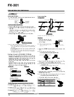
Mounting

1

Fit the rear part of the amplifier on
a 35 mm 

1.378 in 

width DIN rail.

2

Press down the front part of the
mounting section of the amplifier on
the 35 mm 

1.378 in

width DIN rail.

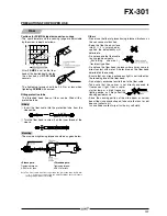
How to mount the amplifier

1

Mount the amplifiers, one by
one, on the 35 mm

1.378 in

width DIN rail.

1

(For details, refer to ‘

Mounting

’.)

2

Slide the sub units next to the
main unit, and connect the
quick-connection cables.

Mount the optional end plates
(

MS-DIN-E

) at both the ends to

hold the amplifiers between
their flat sides.

4

Tighten the screws to fix the

end plates (

MS-DIN-E

).

Cascading method

Connection

1

Holding the connector of the
quick-connection cable, align its
projection with the groove at
the top portion of the amplifier
connector.

2

Insert the connector till a click
is felt.

Connection method

1

Pressing the projection at the top of
the quick-connection cable connector,
pull out the connector.

Disconnection method

Cascading amplifiers

1

Push the amplifier forward.

2

Lift up the front part of the
amplifier to remove it.

Note: Take care that if the front part is lifted without pushing the amplifier

forward, the hook on the rear portion of the mounting section is likely to
break.

How to remove the amplifier

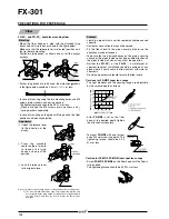
1

Snap the fiber lock lever down.

2

Insert fiber cables slowly into the
inlets until they stop. (Note 1)

3

Return the fiber lock lever
to the original position, till
it stops.

Notes: 1) In case the fiber cables are not inserted to a position where they

stop, the sensing range reduces.

Notes:

2) With the coaxial reflective type fiber, such as, 

FD-G4

or 

FD-FM2

,

insert the single-core fiber cable into the beam-emitting inlet and
the multi-core fiber cable into the beam-receiving inlet. If they are
inserted in reverse, the sensing accuracy will deteriorate.

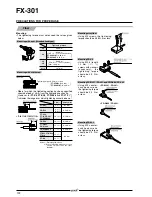
Note: Take care that it the connector is pulled out

without pressing the projection, the projection
may break. Do not use a quick-connection
cable whose projection has broken.

Note:

Further, do not pull by holding the cable, as
this can cause a cable-break.

How to connect the fiber cables

Amplifier

35 mm 

1.378 in 

width DIN rail

Make sure that the power supply is off while connecting
or disconnecting the quick-connection cable.

Part description

1

Loosen the screws of the end
plates (

MS-DIN-E

).

2

Remove the end plates (

MS-DIN-E

).

3

Slide the sub units and remove
them one by one.

3

(For details, refer to ‘

Mounting

’.)

Dismantling

Operation procedure

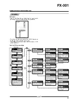
When the power supply is switched on, communication

self-check is carr ied out and nor mal condition is
displayed [MODE indicator / RUN (green) lights up and
the digital display shows incident light intensity].

When MODE key is pressed, the mode changes as per the diagram below.

When jog switch is pressed, the setting is confirmed.
When MODE key is pressed for 2 sec., or more, the sensor returns to the RUN mode.
Cancellation is possible by pressing MODE key during setting.

1

Loosen the screws of the end
plates (

MS-DIN-E

).

2

Remove the end plates (

MS-DIN-E

).

3

Slide the sub units and remove
them one by one.

3

(For details, refer to ‘

Mounting

’.)

Summary of Contents for Digital Fiber Sensor FX-301

Page 1: ...ible so that a stable light emitting level is maintained There is very little element deterioration so that stable and accurate sensing can be maintained over long periods Our new fiber cutter utilizes a specially developed two in one fiber attachment that now makes it possible to cut two fibers simultaneously to exactly the same length Also since the fibers can be attached to the amplifier while ...

Page 2: ...y one output line a great amount of wiring and space can be saved Also special sliding connectors have been provided for all main and sub cables which can be detached merely by releasing the lock and pulling directly back without having to slide the amplifier body to the side Using this connector system only a minimal amount of space is required for regular maintenance The use of only two switches...

Page 3: ...ction is useful for sensing only objects taking a long time travel OFF delay timer This function is useful when the connected device has a slow response time ONE SHOT timer This function is useful when the input specifications of the connected device require a signal of fixed width Optical communication function lets multiple sensors be adjusted all at once The optical communication function allow...

Page 4: ...aking it ideal for delicate sensing Sensing register marks The green LED type can accurately discriminate between red and yellow that cannot be easily detected using red LED type Sensing film meandering Infrared LED type is ideal for sensing environments with light restrictions such as places where light sensitive film is being handled The emission peak wavelength 940 nm 0 037 mil It includes full...

Page 5: ...scading multiple amplifiers or when it moves depending on the way it is installed on a DIN rail these end plates ensure that all amplifiers are mounted together in a secure and fully connected manner End plates Quick connection cable is not supplied with the amplifier Please order it separately Quick connection cable is not supplied with the amplifier Please order it separately Two pcs per set OPT...

Page 6: ... 480 18 898 168 6 614 780 30 709 400 15 748 130 5 118 700 27 559 360 14 173 126 4 961 530 20 866 230 9 055 80 3 150 2 000 78 740 1 000 39 370 350 13 780 400 15 748 200 7 874 70 2 756 390 15 354 180 7 087 63 2 480 175 6 890 80 3 150 27 1 063 270 10 630 49 1 929 R10 mm R0 394 in R10 mm R0 394 in Elbow Side view With lens With lens Lens mountable Lens mountable Lens mountable Lens mountable Sleeve 90...

Page 7: ... 118 H0 472 D0 315 Easy mounting Front sensing Side view type with small light dispersion W8 5 H12 D3W0 335 H0 472 D0 118 Easy mounting Top sensing W3 H8 D12W0 118 H0 315 D0 472 Easy mounting Side sensing W3 H12 D8W0 118 H0 472 D0 315 Easy mounting Front sensing W8 5 H12 D3W0 335 H0 472 D0 118 Sleeve part cannot be bent Notes 1 Please take care that the sensing range of the free cut type fiber may...

Page 8: ...7 Sensing width 11 mm 0 433 in W4 2 H31 D13 5 W0 165 H1 220 D0 531 Top sensing W5 H15 D15W0 197 H0 591 D0 591 Side sensing W5 H15 D15W0 197 H0 591 D0 591 Side view Beam diameter 0 125 mm 0 005 in Notes 1 Please take care that the sensing range of the free cut type fiber may be reduced by 20 max depending upon how the fiber is cut In addition the infrared type is easily affected by humidity so cont...

Page 9: ...ust changes to light incident operation in the object absent condition Notes 3 The allowable cutting range is 500 mm 19 685 in from the end that the amplifier inserted Lens mountable Side view 350 C 662 F Lens mountable 200 C 392 F Lens mountable 130 C 266 F Lens mountable Easy mounting Rectangular head SEMI S2 compliant W7 H15 D13 W0 276 H0 591 D0 512 350 C 662 F Sleeve 60 mm 2 362 in Allows flex...

Page 10: ...2 30 1 181 20 0 787 10 0 394 7 0 276 20 0 787 10 0 394 7 0 276 20 0 787 10 0 394 7 0 276 6 0 236 3 0 118 2 0 079 20 0 787 10 0 394 7 0 276 20 0 787 10 0 394 7 0 276 4 0 157 2 0 079 1 5 0 059 6 0 236 3 0 118 2 0 079 10 0 472 5 0 197 3 0 118 4 0 157 Notes 1 The sensing range is specified for white non glossy paper FD B8 FD 5 FD FM2 FD FM2S FD FM2S4 FD N8 FD T80 FD S80 and FD R80 400 400 mm 15 748 15...

Page 11: ...t 8 0 315 Cannot use 11 0 433 5 5 0 217 3 0 118 2 0 079 1 0 039 11 0 433 5 5 0 217 3 0 118 2 0 079 1 0 039 5 0 197 2 5 0 098 1 5 0 059 18 0 709 9 0 354 6 0 236 8 0 315 4 0 157 2 5 0 098 2 0 079 1 0 039 7 0 276 3 5 0 138 2 0 079 Notes 1 The sensing range is specified for white non glossy paper 100 100 mm 3 937 3 937 in FD WKZ1 FD W8 FD WT8 FD WS8 and FD P80 400 400 mm 15 748 15 748 in FD WG4 FD WSG...

Page 12: ... 512 22 0 866 11 0 433 8 0 315 6 0 236 3 0 118 2 0 079 5 0 197 2 0 079 1 0 039 2 0 079 1 0 039 2 0 079 1 0 039 6 0 236 3 0 118 2 0 079 6 0 236 3 0 118 2 0 079 4 5to9 5 0 177to0 374 5to9 0 197to0 354 5 5to8 0 217to0 315 32 1 260 16 0 630 10 0 394 22 0 866 11 0 433 6 0 236 18 0 709 9 0 354 5 0 197 12 0 472 6 0 236 4 0 157 3 0 118 1 5 0 059 1 0 039 2 0 079 1 0 039 1 0 039 1 0 039 3 0 118 1 5 0 059 1 ...

Page 13: ...84 in R25 mm R0 984 in R200 mm R7 874 in 2 m 6 562 ft 1 m 3 281 ft 1 m 3 281 ft 1 m 3 281 ft Allowable bending radius Model No The vacuum type fiber must be used with the following products as a set FT J6 Fiber at atmospheric side one pair set FV BR1 Photo terminal one pair set 300 C 572 F Glass substrate detection Fixed focus reflective type W19 H27 D5 W0 748 H1 063 D0 197 180 C 356 F Glass subst...

Page 14: ...arrow and alignment is difficult Especially when installing a fiber with many cores sharp bending fibers and heat resistant glass fiber please be sure to use it only after you have adjusted it sufficiently Notes 2 The sensing ranges are the values for red LED type amplifier Please contact our office for details on sensing ranges for other types of amplifiers Notes 3 The fiber cable length practica...

Page 15: ...ective tube made of non corrosive stainless steel protects the inner fiber cable from any external forces FT B8 FT NB8 FT FM2 FT FM2S FT FM2S4 FT N8 FT P80 FT P60 FT H13 FM2 FT T80 FT NFM2 FT NFM2S FT NFM2S4 FT P40 FD T40 FD P40 FD B8 FD FM2 FD FM2S FD FM2S4 FD N8 FD P80 FD H13 FM2 FD T80 FD N4 FD NFM2 FD NFM2S FD NFM2S4 For M3 thread For M6 thread For M4 thread Applicable fibers Model No Descript...

Page 16: ...ach 98 m s2 acceleration 10 G approx in X Y and Z directions for five times each Enclosure Heat resistant ABS Case cover Polycarbonate Switch Acrylic Connector Note 3 Extension up to total 100 m 328 084 ft is possible with 0 3 mm2 or more cable 25 g approx Supply voltage Power consumption Output Utilization category Output operation Short circuit protection Response time Sensitivity setting Operat...

Page 17: ...55 C 40 to 131 F 35 to 85 RH No dew condensation or icing allowed Acrylic Polyethylene Stainless steel SUS including sleeve FT W8 W4 FD W8 W44 WG4 Brass Nickel plated Case of FT WA30 WA8 WZ8 Lens of FT WS8L and Resin part of FT WKV8 Polycarbonate Lens of FT WA30 Norbornene resin Lens of FT WA8 Polyolefin Lens of FT WZ8H WZ8E Reflector of FT WZ8E and Prism of FT WKV8 Acrylic Reflector of FT WZ8 Pol...

Page 18: ...2 pcs and nuts 2 pcs R10 mm R0 394 in or more 40 to 60 C 40 to 140 F FD P81X 40 to 70 C 40 to 158 F Polyethylene FT P81X Vinyl chloride Protective tube Stainless steel SUS FT P81X FD P81X Brass Nickel plated FD G6X Stainless steel SUS All fibers 1 fiber attachment set nuts 2 pcs thru beam type 4 pcs and toothed lock washer 1 pc thru beam type 2 pcs FD G6X FX CT2 fiber cutter 1 pc Allowable bending...

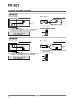
Page 19: ... arrangement diagram NPN output type PNP output type Note The quick connection sub cable does not have brown lead wire and blue lead wire I O circuit diagram Wiring diagram Notes 1 The quick connection sub cable does not have V brown and 0 V blue Notes 2 50 mA max if five amplifiers or more are connected together Symbols D Reverse supply polarity protection diode ZD Surge absorption zener diode Tr...

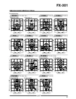
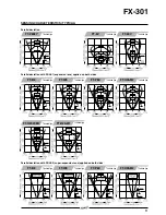
Page 20: ...80 FT V10 FT SFM2SV2 FT V22 FT V41 L Thru beam type Thru beam type Thru beam type Thru beam type Thru beam type Thru beam type Thru beam type Thru beam type Thru beam type Thru beam type Thru beam type Thru beam type Horizontal direction Vertical direction Horizontal direction Vertical direction Horizontal direction Vertical direction Horizontal direction Vertical direction ...

Page 21: ...eam type Thru beam type Parallel deviation FT WA30 FT A30 FT WA8 FT A8 L Thru beam type Thru beam type Horizontal direction Vertical direction Horizontal direction Vertical direction Horizontal direction Vertical direction Horizontal direction Vertical direction FT WKV8 Thru beam type Horizontal direction Vertical direction SENSING CHARACTERISTICS TYPICAL ...

Page 22: ...irection FT Z8 FT P80 FT P60 FT P40 Thru beam type Thru beam type Thru beam type Thru beam type FT Z8H FT Z8E Thru beam type Thru beam type FT P2 FT PS1 Thru beam type Thru beam type FT AFM2 Thru beam type Horizontal direction Vertical direction FT AFM2E Thru beam type FT K8 L Thru beam type SENSING CHARACTERISTICS TYPICAL ...

Page 23: ...tion Vertical direction FT P81X FT H35 M2 FT H35 M2S6 FT H20W M1 FT H20W M2 FT H20 M1 Thru beam type Thru beam type Thru beam type Thru beam type FT E12 FT E22 Thru beam type Thru beam type FT H13 FM2 FT L8Y Thru beam type Thru beam type FT V8Y Thru beam type Horizontal direction Vertical direction SENSING CHARACTERISTICS TYPICAL ...

Page 24: ...applied on both sides Parallel deviation with FX LE1 expansion lens applied on both sides FT B8 FT W8 FT P80 FT H35 M2 Thru beam type Thru beam type Thru beam type Thru beam type FT H20W M2 FT H20 M1 Thru beam type Thru beam type FT B8 FT W8 FT P80 FT H35 M2 Thru beam type Thru beam type Thru beam type Thru beam type SENSING CHARACTERISTICS TYPICAL ...

Page 25: ...Thru beam type Horizontal direction FT P80 Thru beam type FT H35 M2 Thru beam type FT H20W M2 Thru beam type FT H20 M1 Thru beam type Vertical direction Horizontal direction Vertical direction Horizontal direction Vertical direction Horizontal direction Vertical direction Horizontal direction Vertical direction SENSING CHARACTERISTICS TYPICAL FT H20W M2 FT H20 M1 FT H13 FM2 Thru beam type Thru bea...

Page 26: ...sing fields FD SFM2SV2 Reflective type Horizontal direction Vertical direction Horizontal direction Vertical direction Horizontal direction Vertical direction FD V41 Reflective type FD W8 FD WT8 FD WS8 FD W44 FD WT4 Reflective type Reflective type FD N8 FD N4 Reflective type Reflective type FD R80 Reflective type FD WKZ1 Reflective type SENSING CHARACTERISTICS TYPICAL ...

Page 27: ... FD EG1 FD EG2 Reflective type Reflective type FD G4 FD G6 Reflective type Reflective type Sensing fields FD P60 FD P50 Reflective type Reflective type FD P40 Reflective type FD P2 Reflective type SENSING CHARACTERISTICS TYPICAL FD WG4 FD WSG4 Reflective type FD P80 Reflective type FD WV42 Reflective type Horizontal direction Vertical direction ...

Page 28: ...fields FD ENM1S1 FD P81X Reflective type Reflective type FD G6X Reflective type FD H35 M2 FD H35 M2S6 Reflective type FD H20 M1 FD H35 20S Reflective type Reflective type FD H20 21 Reflective type FD H30 L32 FD H18 L31 Reflective type FD H13 FM2 FD 6V Reflective type Reflective type SENSING CHARACTERISTICS TYPICAL ...

Page 29: ...ion method 1 Pressing the projection at the top of the quick connection cable connector pull out the connector Disconnection method Cascading amplifiers 1 Push the amplifier forward 2 Lift up the front part of the amplifier to remove it Note Take care that if the front part is lifted without pushing the amplifier forward the hook on the rear portion of the mounting section is likely to break How t...

Page 30: ...onditions After this the judgment on the stability of sensing is displayed In case stable sensing is possible is displayed Stability indicator green blinks In case stable sensing is not possible blinks Stability indicator green is off After this the judgment on whether the setting shift amount can be shifted or not is displayed In case shifting is possible blinks In case shifting is not possible b...

Page 31: ... H P if jog switch and MODE key are pressed for more than 3 sec at the same time in RUN mode condition the key operations are locked and only the threshold value confirmation function or the adjust function valid only when the adjust lock function is canceled is valid To cancel the lock function press both the keys for more than 3 sec once again Wiring Make sure that the power supply is off while ...

Page 32: ...ode settings Refer to the Fiber Sensor Guide Book for more details pertaining to the PRO mode settings and procedures The above can also be download from SUNX fiber sensor homepage http www fiber sensor com PRO settings can be done when MODE indicator PRO yellow lights up ...

Page 33: ...e fixed at mm from the tightening section tip However for FT K8 FT KV8 FT WKV8 and FT V10 indicates the range over which tightening cannot be done Mounting with a nut threaded head type Mounting with a set screw Mounting array fiber Tightening torque mm in Tightening torque Tightening torque 0 29 N m or less FT SFM2L 0 19 N m FT H20W M 0 49 N m FT K8 FT KV8 FT WKV8 FT V10 Using M3 counter sunk hea...

Page 34: ...In case of tapping the mounting section In case of using attached screw and nut Using M3 pan head screws the tightening torque should be 0 3 N m or less Mounting FT Z802Y If not using the attached mounting brackets Use M3 or less set screws cup point and affix the head within 15 mm 0 591 in from the tip of the fiber head Do not exceed a torque of 0 3 N m when tightening If using the attached mount...

Page 35: ... At the time of installation determine a reference plane as shown in the figure below and taking sufficient care against beam misalignment or tilt install the emitting and receiving fibers so that they are parallel FT K8 Narrow beam type fiber mounting Install the fiber using M3 countersunk head screws The tightening torque should be 0 3 N m or less Further when using the fiber at places having in...

Page 36: ...nlock the fiber cables press the fiber lock button towards unlock direction from the opposite side 4 Insert the fiber cables into the holes for 2 2 mm 0 087 in fiber cables of the fiber cutter FX CT2 from the direction shown in the figure right FX AT3 Attachment for 2 2 mm 0 087 in fiber clear orange FX AT4 Attachment for 1 mm 0 039 in fiber black FX AT5 Attachment for 1 3 mm 0 051 in fiber gray F...

Page 37: ...h the upper portion of the fiber head as shown in the figure below Sensing range when mounting slit mask with FX 301 P Mounting Slit masks FT WA30 A30 2 500 mm 98 425 in LONG 1 000 mm 39 370 in STD 600 mm 23 622 in FAST 200 mm 7 874 in S D FT WA8 A8 400 mm 15 748 in LONG 200 mm 7 874 in STD 140 mm 5 512 in FAST 70 mm 2 756 in S D 0 5 12 mm 0 020 0 472 in slit mask FT WA8 A8 800 mm 31 496 in LONG 4...

Page 38: ...be damaged under the value The bending radius of the bear fiber should be R25 mm R0 984 in or more The sensing range will be shortened under the value Do not subject the fiber under tension Although the chemical resistant type fiber is rated for use up to 115 C 239 F place 100 mm 3 937 in or more of the fiber in the normal temperature area to protect the amplifier FD F8Y liquid level sensing fiber...

Page 39: ...using the two mounting holes use M3 screws plain washers and spring washers The tightening torque should be 0 5 N m or less Please arrange the M3 screws plain washers and spring washers separately In case of mounting on the pipe with tying bands the fiber position can be easily adjusted Adjustment 1 Unlock the release lever in the direction of the arrow 2 Press the movable center holders forward t...

Page 40: ...81 in or more to connect it to the amplifier Make sure to measure the length required before cutting Others Do not use the fiber at places having intense vibrations as this can cause malfunction Keep the fiber head surface intact If it is scratched or spoiled the detectability will deteriorate Do not expose the fiber cable to any organic solvents Excluding chemical resistant type fiber Do not use ...

Page 41: ...ket Optional MS DIN 2 End plate Optional MS DIN E Model No CN 71 C1 CN 71 C2 CN 71 C5 Length mm in 1 000 39 370 2 000 78 740 5 000 196 850 Length L Model No CN 73 C1 CN 73 C2 CN 73 C5 Length mm in 1 000 39 370 2 000 78 740 5 000 196 850 Length L Amplifier FX 301 FX 301 P Material Cold rolled carbon steel SPCC Uni chrome plated Material Polycarbonate ...

Page 42: ... 5 0 335 FT FM2S FT FM2S4 FT T80 FT SFM2 FT N8 FT NFM2 Thru beam type fibers With FX AT3 Free cut With FX AT3 Free cut With FX AT3 Free cut With FX AT5 Free cut Free cut With FX AT3 Free cut Free cut With FX AT3 Free cut With FX AT3 Free cut With FX AT4 FT NFM2S FT NFM2S4 20 0 787 FT SNFM2 Free cut With FX AT4 Free cut With FX AT4 ...

Page 43: ...ru beam type fibers With FX AT3 With FX AT2 Free cut With FX AT3 With FX AT5 Free cut Free cut With FX AT3 With FX AT3 Free cut Free cut With FX AT4 Free cut With FX AT3 Free cut With FX AT5 FT WZ8 FT WKV8 Free cut With FX AT5 Free cut With FX AT3 Details of screw tightening range Note The emiter and receiver are symmetric ...

Page 44: ...t With FX AT4 With FX AT5 Free cut Free cut With FX AT3 With FX AT3 Free cut Free cut With FX AT4 Free cut With FX AT5 Free cut With FX AT5 FT P80 FT P60 Free cut Free cut With FX AT5 Details of sensing part Details of sensing part Details of sensing part Details of sensing part Details of sensing part Details of sensing part Details of sensing part Note The emitter and receiver are symmetric ...

Page 45: ...bers With FX AT4 With FX AT2 Free cut With FX AT3 Free cut With FX AT3 Free cut With FX AT2 With FX AT3 With FX AT3 Free cut Free cut With FX AT3 Free cut With FX AT3 Free cut With FX AT4 FT E12 FT E22 With FX AT2 With FX AT2 Details of sensing part Details of screw tightening range Details of sensing part Details of sensing part ...

Page 46: ...8 5 0 335 Stainless steel SUS FT H35 M2S6 FT H20W M1 FT H20W M2 FT H20 M1 FT H13 FM2 15 0 591 FT Z802Y FT L8Y FT V8Y Thru beam type fibers With FX AT2 With FX AT2 Free cut With FX AT3 Free cut With FX AT3 Free cut With FX AT3 Free cut With FX AT3 FT 6V FT 60V Details of sensing part ...

Page 47: ...ith FX AT2 With FX AT3 Free cut Free cut With FX AT4 Free cut Free cut With FX AT4 FD NFM2S FD NFM2S4 FD SNFM2 Free cut With FX AT4 Free cut With FX AT4 Details of sensing part Details of sensing part Details of sensing part Details of sensing part Details of sensing part Details of sensing part Details of sensing part Details of sensing part Details of sensing part Details of sensing part Details...

Page 48: ...Free cut Free cut With FX AT4 With FX AT4 With FX AT3 Free cut Free cut With FX AT4 Free cut With FX AT5 Free cut With FX AT6 FD WSG4 FD WL41 Free cut With FX AT6 Free cut With FX AT4 Details of sensing part Details of sensing part Details of sensing part Details of sensing part Details of sensing part Details of sensing part Details of sensing part Details of sensing part Details of sensing part ...

Page 49: ...th FX AT2 With FX AT3 With FX AT6 Free cut Free cut Free cut Free cut With FX AT4 With FX AT5 With FX AT4 With FX AT3 With FX AT3 With FX AT6 Free cut Free cut Free cut Free cut FD G4 FD G6 Free cut Free cut Details of sensing part Details of sensing part Details of sensing part Details of sensing part Details of sensing part Details of sensing part Details of sensing part ...

Page 50: ... With FX AT2 FD E12 3 2 0 126 Model No tube PVC FD E22 FD EG3 15 0 591 15 0 591 FD EN500S1 FD ENM1S1 FD L43 Free cut Details of sensing part Details of sensing part Details of sensing part Details of sensing part Details of sensing part Details of sensing part Details of sensing part Reflective type fibers ...

Page 51: ...With FX AT4 With FX AT3 With FX AT2 With FX AT4 With FX AT4 With FX AT6 Free cut FD L4 Free cut FD F41 FD F91 FD F4 FD F9 Free cut FD F8Y Free cut Toothed lock washer 11 0 433 FD P81X FD G6X Free cut Details of sensing part Details of sensing part Reflective type fibers ...

Page 52: ... With FX AT3 Free cut Free cut With FX AT3 FD 6V FX LE1 Details of sensing part Details of sensing part Details of sensing part Details of sensing part Details of sensing part Details of sensing part Details of sensing part Reflective type fibers Expansion lens Optional Material Enclosure Brass Nickel plated Lens Glass ...

Page 53: ...s steel SUS303 Lens Glass Material Enclosure Brass Nickel plated Lens Glass Note In order to obtain a 0 5 mm 0 02 in spot it is necessary to keep in the above figure within the specified range Material Enclosure Aluminum Black ALMITE Lens Glass Notes 1 In order to obtain a 0 3 mm 0 012 in spot it is necessary for in the above figure to be 28 5 mm 1 122 in Notes 2 When inserting the fiber insert it...

Page 54: ...l blade Material POM Materials Holder PA Nylon66 Ground POM Materials Holder PA Nylon66 Ground POM Materials Holder PA Nylon66 Ground POM Model No FTP 500 FTP N500 FDP N500 FDP 500 FTP 1000 FTP N1000 FDP N1000 FDP 1000 FTP 1500 FTP N1500 FDP N1500 FDP 1500 Length L mm in 500 19 685 1 000 39 37 1 500 59 055 10 0 10 0 10 0 0 394 0 0 394 0 0 394 0 Accessory for FD WKZ1 Fiber bender Optional Fiber cut...

Page 55: ... mounting in the side by side configuration The main and sub unit functions are distinguished only by the proper use of 3 core main cable and the 1 core sub cable Moreover by utilizing the same body for both main and sub units inventory management and maintenance is simplified Flashing function incorporated Long life and stable operational settings assure dependable performance When the leak detec...

Page 56: ...selected from the digital display Amplifiers Type Appearance Model No Emitting element Output FX 301 F FX 301P F NPN output PNP output Red LED NPN open collector transistor PNP open collector transistor ORDER GUIDE Quick connection cable is not supplied with the amplifier Please order it separately CN 73 C1 CN 73 C2 CN 73 C5 CN 71 C1 CN 71 C2 CN 71 C5 Length 1 m 3 281 ft Length 2 m 6 562 ft Length...

Page 57: ...esidual voltage 1 5 V or less at 100 mA 50 mA if five or more amplifiers are connected in cascade source current OPTIONS End plates Appearance Model No Description MS DIN E When cascading multiple amplifiers or when it moves depending on the way it is installed on a DIN rail these end plates ensure that all amplifiers are mounted together in a secure and fully connected manner Amplifier mounting b...

Page 58: ...Symbols D Reverse supply polarity protection diode ZD Surge absorption zener diode Tr NPN output transistor Symbols D Reverse supply polarity protection diode ZD Surge absorption zener diode Tr PNP output transistor ...

Page 59: ...scading method 1 Loosen the screws of the end plates MS DIN E 2 Remove the end plates MS DIN E 3 Slide the sub units and remove them one by one For details refer to Mounting Dismantling method This product is not a safety sensor Its use is not intended or designed to protect life and prevent body injury or property damage from dangerous parts of machinery It is a normal object detection sensor 1 F...

Page 60: ...ting at the time of factory shipment is Liquid F9 mode Notes 3 Do not move or bend the fiber cable after the sensitivity setting Detection may become unstable 1 Operation indicator Orange Lights up when output is ON 2 Model indicator Green Lights up during liquid setting F9 mode 3 MODE indicators RUN Green Lights up during normal sensing operation TEACH Yellow Lights up when the individual teachin...

Page 61: ...mplifier is set Notes 3 When the collective teaching is done the setting conditions are copied In case an individual setting condition is desired to be set set it individually after the collective teaching Notes 4 Do not move or bend the fiber cable after the sensitivity setting Detection may become unstable Notes 5 The collective teaching transmits the information only in the direction of the arr...

Page 62: ...ODE indicator RUN green blinks When Jog switch is turned to the side or side the display and MODE indicator RUN green blinks and the timer period can be chosen Without timer 10 ms timer 100 ms timer 1 000 ms timer When Jog switch is pressed setting display blinks 3 times and is confirmed The sensor returns to step 2 When MODE key is pressed twice or for 1 sec or more the sensor returns to RUN mode...

Page 63: ... from a rapid starter lamp or a high frequency lighting device as it may affect the sensing performance Avoid dust dirt and steam When the fiber head gets dusty or dirty etc the sensitivity deteriorates To keep stable detection wipe the fiber head to remove dust or dirt etc and carry out sensitivity teaching periodically This sensor is suitable for indoor use only Take care that the product does n...

Page 64: ...527 FX 301 F ...
Page 65: ...n addition the second output channel can be used for simple self diagnosis and alarm output so that ease of maintenance is improved During STDF LONG and U LG modes High speed response that is about twice as fast as before has been achieved Even small objects moving at high speeds can be sensed In addition interference between two units is prevented in high speed mode H SP Comparison of saturation ...

Page 66: ...corporated Up to 4 sets of fiber heads can be mounted close together However U LG mode is 8 sets H SP mode is 2 sets H SP 65 s or less FAST 150 s or less STD 250 s or less STDF 700 s or less LONG 2 5 ms or less U LG 4 5 ms or less selectable with jog switch Incorporated with variable ON delay OFF delay ONE SHOT ON delay OFF delay ON delay ONE SHOT timer switchable either effective or ineffective T...

Reviews: