background image

ENGLISH –


83

Special Features

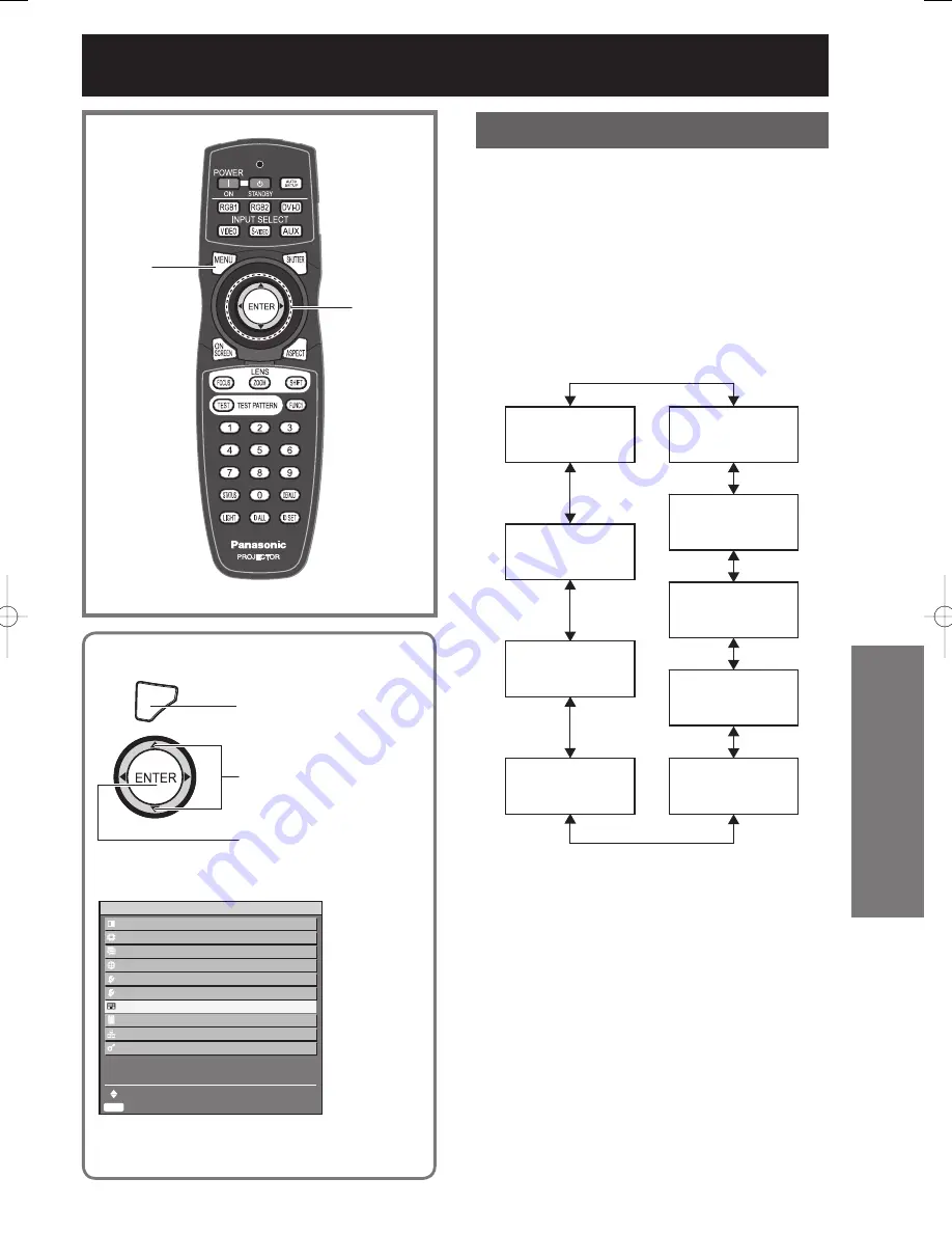
The projector has 8 types of internal test patterns 
to check the condition of the set.

MENU

Press to display the 
MAIN MENU screen.

Press to select “TEST 
PATTERN”.

Press to display the 
“TEST PATTERN” 
screen.

MENU

Press to display the 
MAIN MENU screen.

Press to select “TEST 
PATTERN”.

Press to display the 
“TEST PATTERN” 
screen.

MAIN MENU

  PICTURE
  POSITION
  ADVANCED MENU
  DISPLAY LANGUAGE
  OPTION1
  OPTION2
  

TEST PATTERN


SIGNAL LIST

  NETWORK
  SECURITY

    MENU SELECT
    SUB MENU

ENTER

MAIN MENU

  PICTURE
  POSITION
  ADVANCED MENU
  DISPLAY LANGUAGE
  OPTION1
  OPTION2
  

TEST PATTERN


SIGNAL LIST

  NETWORK
  SECURITY

    MENU SELECT
    SUB MENU

ENTER

 Test pattern

Results of adjustment on the image, picture quality, 
position, size and other factors will not be reflected 
in test patterns. Be sure to display the input signal 
before performing various kinds of setting.

1. Press 

◄►

 to search through the 

various types of test patterns.

Cycle of displayed internal test 
patterns

The setting will change as follows each time 

◄►


is pressed.

MENU screen

+

Entry screen

MENU screen

+

All white

MENU screen

+

All black

MENU screen

+

Flag

MENU screen

+

Flag (inversion)

MENU screen

+

Focus

MENU screen

+

Color bars

MENU screen

+

Window (inversion)

MENU screen

+

Window

▲▼◄►

ENTER

MENU

Displaying the internal test pattern

Summary of Contents for D10000U - SXGA+ DLP Projector

Page 1: ...TQBJ 0208 Operating Instructions DLP Based Projector Commercial Use PT D10000U PT DW10000U Read these instructions completely before operating this unit Models No ...

Page 2: ... will help you to get the most performance out of your new product and that you will be pleased with your Panasonic DLP based projector The serial number of your product may be found on its back You should note it in the space provided below and retain this booklet in case service is required Model number PT D10000U PT DW10000U Serial number ...

Page 3: ...ing the picture 49 Adjusting the position 56 How to use ADVANCED MENU 60 Setting the DISPLAY LANGUAGE 66 Option1 settings 67 Option2 settings 75 Displaying the internal test pattern 83 How to use network function 84 Using the PJLink protocol 98 Setting the security 99 Using the serial terminals 102 Using the Remote 2 terminal 106 Indication of monitor lamp 107 Cleaning and replacement of air filte...

Page 4: ...f electric shock to persons The exclamation point within an equilateral triangle is intended to alert the user to the presence of important operating and maintenance servicing instructions in the literature accompanying the product CAUTION This equipment is equipped with a three pin grounding type power plug Do not remove the grounding pin on the power plug This plug will only fit a grounding type...

Page 5: ...elp FCC CAUTION To assure continued compliance use only shielded interface cables when connecting to computer or peripheral devices Any unauthorized changes or modifications to this equipment could void the user s authority to operate WARNING Not for use in a computer room as defined in the Standard for the Protection of Electronic Computer Data Processing Equipment ANSI NFPA 75 Declaration of Con...

Page 6: ...t cover the air filter the air inlet and exhaust vents Doing so may cause the projector to overheat which can cause fire or damage to the projector Do not overload the wall outlet If the power supply is overloaded for example by using too many adapters overheating may occur and fire may result Do not remove the cover or modify it in any way High voltages which can cause fire or electric shocks are...

Page 7: ...f children The battery can cause death by suffocation if swallowed If the battery is swallowed seek medical advice immediately Do not allow the and terminals of the battery to come into contact with metallic objects such as necklaces or hairpins Failure to observe this may cause the battery to leak overheat explode or catch fire Store the battery in a plastic bag and keep it away from metallic obj...

Page 8: ...may result When inserting the battery make sure the polarities and are correct If the battery is inserted incorrectly it may explode or leak and fire injury or contamination of the battery compartment and surrounding area may result Use only the specified battery If an incorrect battery is used it may explode or leak and fire injury or contamination of the battery compartment and surrounding area ...

Page 9: ...nside of the projector Ask an Authorized Service Center to clean inside the projector at least once a year If dust is left to build up inside the projector without being cleaned out it can result in fire or problems with operation It is a good idea to clean the inside of the projector before the season for humid weather arrives Ask your nearest Authorized Service Center to clean the projector when...

Page 10: ...s may be transmitted to the product to damage the internal parts causing failure Install the product in a place free from vibrations and impacts Do not install the projector near high voltage power lines or power sources The product may be exposed to interference if it is installed in the vicinity of high voltage electrical power lines or power sources Do not place the projector on a vinyl sheet o...

Page 11: ...ces or leave flaws or stains on the screen Lamp A mercury lamp with high internal pressure is used for the light source of this product A high pressure mercury lamp has the following characteristics It may burst with a loud sound or end its life cycle by not illuminating because of given impacts flaws or deterioration due to used hours The life cycle of a mercury lamp varies according to the indiv...

Page 12: ...just the level Also use them to enter the SECURITY password ENTER button p 48 Press this button to enter your menu selection or to run function ON SCREEN button p 43 This button turns on and off the on screen indication function TEST PATTERN button p 44 This displays the test pattern Numeric 0 9 buttons pp 18 82 These buttons are used for systems where more than one projector is being used They ar...

Page 13: ...remote control 7 ID ALL button pp 18 75 When two or more main units are used in the system this button switches to the mode to control them simultaneously with a single remote control 8 LOCK button This button is used to prevent unintentional operation of the projector by accidentally pressing a button and to prevent the remote control batteries from becoming spent 9 Remote control transmitter win...

Page 14: ...ar hook Attach a commercial burglar prevention cable to this hook port Adjustable feet p 20 Use these feet to adjust the tilt of the projector Adjustable feet are provided at the front and rear right and left Projection lens cover lock button p 33 This button toggles between lock and unlock of the detachable cover for the projection lens optional Air filter p 108 0 Air filter cleaning monitor pp 8...

Page 15: ... holding down the MENU button for at least 3 seconds while the on screen indication function is OFF Arrow buttons pp 48 99 Use to select an item on the menu screen change setting and adjust the level Also use them to enter the SECURITY password LENS button p 37 Switches to the adjustment mode for lens focus zoom and shift position ENTER button p 48 Press this button to enter your menu selection or...

Page 16: ...terminal pp 26 102 105 This terminal is an RS 422 compliant output terminal switching necessary to supply signals given to the serial input terminal D SUB 9 pin male LAN terminal 10BASE T 100BASE TX pp 25 26 85 This terminal is used for connecting a LAN cable VIDEO IN terminal p 25 An input terminal for video signals BNC VIDEO OUT terminal p 25 An output terminal active through for video signals B...

Page 17: ...ally be aimed at either the front or rear remote control receiver window on the projector figure 1 The effective control range is approx 30 metres from the beam receiver on the front or rear Otherwise it may also be aimed at the screen which will reflect commands back to the projector s front receiver window as illustrated in figure 2 When the Remote Control is aimed at the screen the effective co...

Page 18: ...ton has been pressed the ID number will remain at the number that was set before the ID SET button was pressed Your specified ID number is stored in the remote control unit unless another one is specified later However the stored ID will be erased if the batteries of the remote control are left exhausted When the batteries are replaced set the same ID number again Using a wired remote control When...

Page 19: ...ystem expansions Both input and output are provided to all terminals on the main unit The following are some examples of system expansion Installation System 1 The optional high or low ceiling mount bracket flexibly fits the projector in individual site conditions System 2 Connection to a computer via the DVI D IN terminal or DVI D input module optional ...

Page 20: ...th the PT D10000U and PT DW10000U If the ET D75LE6 has been installed the values will be H 0 1 SH to 0 9 SH for the PT D10000U and H 0 to SH for the PT DW10000U L 175 254 200 SW 314 120 66 12 4 4 7 2 6 6 9 10 7 9 L1 Top View unit mm inch Screen Side View unit mm inch Screen L Projection distance SW Image width SH Height of the image H Vertical distance between the lens Center level and the bottom ...

Page 21: ...46 11 21 50 70 6 21 51 70 6 35 96 117 11 35 97 118 57 28 187 11 57 00 187 107 15 351 6 7 19 23 7 8 61 28 2 400 4 981 16 4 8 855 29 12 19 39 11 16 29 53 5 16 38 53 8 24 58 80 7 24 60 80 8 41 12 134 10 41 12 134 10 65 47 214 9 65 19 213 10 122 51 401 11 8 22 26 11 9 85 32 3 500 6 226 20 5 11 069 36 3 15 26 50 20 39 66 10 20 50 67 3 30 76 100 11 30 77 100 11 51 42 168 8 51 43 168 8 81 87 268 7 81 59 ...

Page 22: ...59 267 8 153 23 502 8 10 29 33 9 12 33 40 5 600 9 144 30 12 192 40 18 33 60 1 24 49 80 4 24 61 80 8 36 93 121 1 36 94 121 2 61 73 202 6 61 74 202 6 98 26 322 4 97 98 321 5 183 95 603 6 12 36 40 6 14 81 48 7 Lens type Zoom lens Fixed focus lens Model number of projection lens ET D75LE1 ET D75LE2 ET D75LE3 ET D75LE4 ET D75LE8 ET D75LE6 ET D75LE5 Throw ratio 1 1 5 2 0 1 2 0 3 0 1 3 0 5 0 1 5 0 8 0 1 ...

Page 23: ...ce L 0 0617 Screen diagonal inch 0 1064 16 9 Minimal distance L 0 0448 Screen diagonal inch 0 0795 Maximal distance L 0 0672 Screen diagonal inch 0 1064 ET D75LE3 3 0 5 0 1 4 3 Minimal distance L 0 0617 Screen diagonal inch 0 0958 Maximal distance L 0 1031 Screen diagonal inch 0 1216 16 9 Minimal distance L 0 0672 Screen diagonal inch 0 0958 Maximal distance L 0 1123 Screen diagonal inch 0 1216 ET...

Page 24: ...d 3 are not assigned and are GND terminals The pin out and signal names of the DVI D IN terminal are shown in the diagram below Outside view Pin No Signal Ground luminance signal Ground color signal Luminance signal Color signal Outside view Pin No Signal Ground luminance signal Ground color signal Luminance signal Color signal Pin No Signal R PR G G SYNC Y B PB 1 HD SYNC 2 VD Outside view Pin No ...

Page 25: ... compliant device but with some devices the images may not appear or other problems may be encountered in operation IN OUT RS 232C IN RS 422 IN RS 422 OUT SERIAL REMOTE 1 REMOTE 2 IN OUT IN SYNC HD VD B PB G Y R PR S VIDEO IN VIDEO RGB 2 IN DVI D IN RGB 1 IN LAN Video deck TBC built in Control PC Control PC Color monitor Video deck TBC built in High vision video deck Red connected to PR terminal B...

Page 26: ...ction properly until the resume capability is disabled IN OUT RS 232C IN RS 422 IN RS 422 OUT SERIAL REMOTE 1 REMOTE 2 IN OUT IN SYNC HD VD B PB G Y R PR S VIDEO IN VIDEO RGB 2 IN DVI D IN RGB 1 IN LAN To 2nd projector SERIAL IN terminal I F PC Control PC Control PC Control PC PC PC IN OUT RS 232C IN RS 422 IN RS 422 OUT SERIAL REMOTE 1 REMOTE 2 IN OUT IN SYNC HD VD B PB G Y R PR S VIDEO IN VIDEO ...

Page 27: ...80 24p 1 080 23 98p RJ 45 input 1 1 10BASE T 100BASE TX DVI D input module ET MD77DV DVI D 24p input 1 HDCP compliant 2 DVI D single link DVI 1 0 compliant EDID1 480p 576p 720 60p 720 59 94p 720 50p 1 080 60i 1 080 59 94i 1 080 50i 1 080 24sF 1 080 23 98sF 1 080 30p 1 080 29 97p 1 080 25p 1 080 24p 1 080 23 98p 1 080 50p 1 080 59 94p 1 080 60p EDID2 Displayable resolution VGA UXGA non interlace Do...

Page 28: ... VIDEO AUTO SETUP MENU LENS SHUTTER LIGHT POWER ON STANDBY ON OFF ENTER 1 Remove the slot cover Remove 2 screws 2 Insert the input module Slot Input module 3 Fix the input module 4 Register the input signal This projector needs to register the type of input signal after the installation of the input module For details on the registration of the input signals refer to pages 40 42 Tighten the two sc...

Page 29: ...NS SHUTTER LIGHT POWER ON STANDBY ON OFF ENTER Business digital VCR DVD player High vision video deck PC SDI signal DVI D signal SD SDI input module ET MD77SD1 HD SD SDI input module ET MD77SD3 DVI D input module ET MD77DV Projector MAIN POWER AC IN OFF ON IN OUT RS 232C IN RS 422 IN RS 422 OUT SERIAL LAN REMOTE 1 REMOTE 2 IN OUT IN SYNC HD VD B PB G Y R PR S VIDEO IN VIDEO RGB 2 IN DVI D IN RGB 1...

Page 30: ... is done the input signal details will appear on the screen momentarily and then disappear automatically 1 The LAN terminal of the input module optional cannot be used with the PT D10000U PT DW10000U Use the LAN terminal that is provided as standard with the projector SD SDI Module ET MD77SD1 IN SERIAL OUT LAN SD SDI input module optional ET MD77SD1 for 480i 576i SD SDI signal SD SDI signal output...

Page 31: ...ors in automatic signal recognition may occur If this happens use the SYSTEM SELECTOR menu to switch the format to the one which matches the signals being input Use a 5CFB or superior cable for connection to transmit the image information without error Example 5CFB 5CFTX 7CFB etc 1 The LAN terminal of the input module optional cannot be used with the PT D10000U PT DW10000U Use the LAN terminal tha...

Page 32: ...MD77DV DVI D IN LAN DVI D input module optional ET MD77DV DVI D signal LAN terminal 1 10BASE T 100BASE TX DVD player or high vision video deck equipped with DVD HDMI terminal PC with DVI output Pin assignments and signal names of DVI D input terminal are listed in the table at right 4 5 Outside view Pin No Signal Pin No Signal T M D S data 2 1 T M D S data 2 2 5V T M D S data 2 4 shield 3 Ground 4...

Page 33: ...button pull the cover forward to remove it 2 Align the mark orange on the projection lens with the mark on the projector and then insert the lens and turn it clockwise until it clicks into place FILTER CLEANING OPEN CLOSE Projection lens cover lock button FILTER CLEANING OPEN CLOSE Projection lens cover lock button Mark orange Mark orange 3 Push the projection lens cover in until it clicks into pl...

Page 34: ... short while the projector will switch to standby mode Indicator status Projector status Off Main power is off Red Lit Standby mode POWER ON button can be pressed so that images can be projected Green Lit Images are being projected on Orange Lit Standby preparation mode After a short while the projector will switch to standby mode Connecting the power cord Insert the accessory power cord securely ...

Page 35: ... the operating environment is low and warm up takes more than 5 minutes the projector will judge that a problem has occurred and the power will be turned off automatically If this happens increase the temperature around the projector so that it is 0 C or higher and then turn on the MAIN POWER switch and the POWER ON switch once more 0 Making adjustment and selection Roughly adjust the focus of the...

Page 36: ...ER OK CANCEL Note Turning on the power supply will not light up the light source lamp if the lamp is in the process of cooling down after turning off the power supply To light up the lamp turn on the power supply again when the lamp has been cooled sufficiently The projector consumes approximately 25 W of power even in standby mode Power indicator lamp lit in red If you re power the projector afte...

Page 37: ...om the other items in the adjustment menu even if the lens is out of focus and the letters are difficult to read The zoom adjustment menu will be displayed only when a lens with zoom function is being used At the projector 1 Press LENS on the control panel on the main unit Pressing the button changes the setup screen in the order of FOCUS ZOOM and SHIFT 2 Press to select an item and adjust it Usin...

Page 38: ...T D10000U PT DW10000U Zoom Lens ET D75LE6 0 2H 0 2H 0 40V 0 40V 0 12V 0 12V 0 12V 0 12V Standard projection position Projected screen width H Projected screen height V 0 50V 0 15V 0 50V 0 15V 0 15V 0 15V 0 15H 0 15H Standard projection position Projected screen width H Projected screen height V ET D75LE1 ET D75LE2 ET D75LE3 ET D75LE4 ET D75LE8 0 3H 0 3H 0 50V 0 50V 0 1V 0 1V 0 1V 0 1V Standard pro...

Page 39: ...rn counterclockwise Turn counterclockwise Turn counterclockwise Turn counterclockwise c Turn counterclockwise Turn counterclockwise Turn counterclockwise Turn counterclockwise Attention When moving the projector return the lens to the home position p 38 and then tighten the 3 fixing screws to secure the lens bracket 1 Remove the projection lens cover and lens p 33 2 Loosen the 3 fixing screws that...

Page 40: ... data items can be registered on each page and the data is registered in the unused memory with the lowest number If all the memories are used the data of the old signals is overwritten in sequence The names of the registered data are automatically determined by the input signals and memory numbers If a menu is being displayed the new signals will be registered at the instant they are input Renami...

Page 41: ...E ENTER DEFAULT 2 Press DEFAULT The ENTRY SIGNAL CLEAR screen will be displayed If the data is not to be cleared press MENU to return to the SIGNAL LIST screen 3 Press ENTER The data of the signal selected is cleared Sub memory The projector is provided with a sub memory function to register plural pieces of image adjustment data even they are determined to be the same signal by the frequency and ...

Page 42: ...UB MEMORY NAME MEMORY NO INPUT fH fV SYNC STATE REGISTER SXGA60 A1 RGB1 64 00kHz 60 00Hz H POS V POS On screen indications Input switching signal switching This shows the registered signal name on the status screen for signal switching Details of registered signal The designation can be set by the sub memory items MEMORY NO A1 1 2 Note Restrictions The maximum sub memory items that can be register...

Page 43: ...s to S VIDEO input Press AUX Switches to optional input module input The AUX button to switch the input is disabled when an optional input module is not connected Note Refer to Connection for details on the input terminals pp 25 26 Status function This shows the projector status It can also be used to send information about the projector s status via e mail 1 Press STATUS on the remote control Not...

Page 44: ...tion menu Automatic adjustment may not be available depending on the machine type of the personal computer Automatic adjustment may not available for synchronization signal of C SYNC and G SYNC Image may be distorted for several seconds during automatic adjustment This is not a malfunction For every supplied signal adjustment is required Automatic adjustment can be cancelled by pressing the MENU b...

Page 45: ... change as follows each time ASPECT is pressed 1 PT D10000U Only 2 PT DW10000U Only Note Some aspect ratios may not be available for selection depending on the input signal Refer to Adjusting the aspect ratio for details p 57 VID AUTO PRIORITY S1 AUTO VID AUTO HV FIT H FIT 2 DEFAULT THROUGH 16 9 1 4 3 2 S4 3 1 VID AUTO PRIORITY S1 AUTO VID AUTO HV FIT H FIT 2 DEFAULT THROUGH 16 9 1 4 3 2 S4 3 1 ...

Page 46: ...AL LIST NETWORK SECURITY MENU SELECT SUB MENU ENTER MAIN MENU The main menu consists of the following 10 menu items When a main menu item is selected the screen changes to a sub menu selection screen SUB MENU The sub menu screen for the selected main menu item appears and you can then set and adjust the various items in the sub menu PICTURE pp 49 55 Note The factory default values may vary dependi...

Page 47: ...MEMORY SUB MENU item COLOR MATCHING LARGE SCREEN CORRECTION AUTO SIGNAL AUTO SETUP BACK COLOR DVI EDID AUX DVI EDID P IN P FUNC1 OSD POSITION OSD MEMORY OPTION2 pp 75 82 TEST PATTERN p 83 SIGNAL LIST pp 40 42 NETWORK pp 84 85 SECURITY pp 99 101 SUB MENU item PROJECTOR ID INSTALLATION ALTITUDE DIRECTION OUTPUT RESOLUTION PT D10000U only LAMP SELECT LAMP RELAY RS 232C SYSTEM INFORMATION AIR FILTER C...

Page 48: ...t screen containing a bar scale will appear as shown in the diagram below when is pressed If no button is operated for approx 5 seconds while the individual adjustment screen is displayed the screen will return to the previous page Returning to the previous screen When the MENU is on the screen pressing the MENU button returns to the previous page When the MAIN MENU is on the screen pressing MENU ...

Page 49: ...al CINEMA The picture becomes suitable for movie sources NATURAL The picture complies with sRGB DYNAMIC The picture becomes suitable for the use in well lighted areas GRAPHIC The picture becomes suitable for input from to the personal computer USER The COLOR TEMP and GAMMA settings can be adjusted Note Factory defaults are GRAPHIC for RGB system and STANDARD for moving images When ENTER is pressed...

Page 50: ...F AUTO 1 PICTURE PICTURE MODE CONTRAST BRIGHTNESS COLOR TINT COLOR TEMP GAMMA SHARPNESS NOISE REDUCTION DYNAMIC IRIS SYSTEM SELECTOR MENU SELECT ADJUST NATURAL 0 0 10 1 DEFAULT DEFAULT 0 OFF OFF AUTO 1 2 Press ENTER The BRIGHTNESS individual adjustment screen will be displayed 3 Press to adjust the level Adjusting Color This adjusts the depth of the colors 1 Press to select COLOR 2 Press ENTER The...

Page 51: ... skin tone toward greenish color Minimum value 31 PICTURE PICTURE MODE CONTRAST BRIGHTNESS COLOR TINT COLOR TEMP GAMMA SHARPNESS NOISE REDUCTION DYNAMIC IRIS SYSTEM SELECTOR MENU SELECT CHANGE NATURAL 0 0 10 1 DEFAULT DEFAULT 0 OFF OFF AUTO 1 PICTURE PICTURE MODE CONTRAST BRIGHTNESS COLOR TINT COLOR TEMP GAMMA SHARPNESS NOISE REDUCTION DYNAMIC IRIS SYSTEM SELECTOR MENU SELECT CHANGE NATURAL 0 0 10...

Page 52: ...ELECT CHANGE NATURAL 0 0 10 1 DEFAULT DEFAULT 0 OFF OFF AUTO 1 PICTURE PICTURE MODE CONTRAST BRIGHTNESS COLOR TINT COLOR TEMP GAMMA SHARPNESS NOISE REDUCTION DYNAMIC IRIS SYSTEM SELECTOR MENU SELECT CHANGE NATURAL 0 0 10 1 DEFAULT DEFAULT 0 OFF OFF AUTO 1 2 Press to switch GAMMA The setting will change as follows each time is pressed Note Separate software is required to select USER1 and USER2 Con...

Page 53: ...ICTURE MODE CONTRAST BRIGHTNESS COLOR TINT COLOR TEMP GAMMA SHARPNESS NOISE REDUCTION DYNAMIC IRIS SYSTEM SELECTOR MENU SELECT CHANGE NATURAL 0 0 10 1 DEFAULT DEFAULT 0 OFF OFF AUTO 1 2 Press to switch DYNAMIC IRIS The setting will change as follows each time is pressed To further adjust the selected compensation amount 3 Select USER in step 2 4 Press ENTER The DYNAMIC IRIS screen will be displaye...

Page 54: ...ENU SELECT CHANGE NATURAL 0 0 10 1 DEFAULT DEFAULT 0 OFF OFF AUTO 1 PICTURE PICTURE MODE CONTRAST BRIGHTNESS COLOR TINT COLOR TEMP GAMMA SHARPNESS NOISE REDUCTION DYNAMIC IRIS SYSTEM SELECTOR MENU SELECT CHANGE NATURAL 0 0 10 1 DEFAULT DEFAULT 0 OFF OFF AUTO 1 How to change the system format Using the menu screen operation enables the user to make the following changes depending on S Video Video i...

Page 55: ... input signals Note Refer to the types of RGB YPBPR DVI D signals compatible with the projector p 118 To display pictures complying with the sRGB standard sRGB is the international color reproduction standard IEC61966 2 1 established by IEC International Electrotechnical Commission To reproduce colors more faithfully in compliance with the sRGB standard perform the following setting procedure 1 Se...

Page 56: ...ct SHIFT 2 Press ENTER The SHIFT screen will be displayed 3 Press to adjust the position For horizontal right and left adjustment For vertical up and down adjustment 4 Press MENU three times The on screen indications disappear and the normal screen appears again ENTER POSITION SHIFT ASPECT ZOOM CLOCK PHASE KEYSTONE MENU SELECT SUB MENU DEFAULT 0 ENTER POSITION SHIFT ASPECT ZOOM CLOCK PHASE KEYSTON...

Page 57: ...nt from that of the panel the pictures are displayed by converting it into the panels aspect ratio 4 3 for PT D10000U and 16 9 for PT DW10000U VID AUTO The projector identifies the video ID VID embedded in the picture signals and displays the picture by automatically switching the screen sizes between 4 3 and 16 9 This function is effective for the NTSC signal input S1 AUTO The projector identifie...

Page 58: ...00 6 Press to switch INTERLOCKED The setting will change as follows each time is pressed OFF The V and H settings are used as the vertical and horizontal zoom ratios respectively ON The zoom ratio is set to the HV setting This allows the pictures to be zoomed at equal vertical and horizontal ratios Note When ASPECT is set to THROUGH ZOOM will not appear Clock phase adjustment Clock phase adjustmen...

Page 59: ...TY MENU SELECT ADJUST 0 0 0 Note Adjust the SUB KEYSTONE or LINEARITY after adjusting the KEYSTONE The variable range of the SUB KEYSTONE or LINEARITY changes in response to the adjusted value of the KEYSTONE SUB KEYSTONE is a function which is used to correct keystone distortion when the lens has been shifted to the left or right Keystone correction can only be carried out for the area at the top...

Page 60: ...pressed AUTO Performs automatic detection and cinema processing factory default OFF Unforced cinema processing 25p FIXED Forced cinema processing 2 2 pulldown is performed when a 576i or 1 080 50i signal is input 30p FIXED Forced cinema processing 2 2 pulldown is performed when a 480i or 1 080 60i signal is input Note In DIGITAL CINEMA REALITY mode the image quality will be deteriorated if 30p FIX...

Page 61: ...utton to move the blanking zone upward button to downward Adjusting the input resolution Input resolution adjustment achieves the best image when the screen flickers or halo is observed around the contour 1 Press to select INPUT RESOLUTION 2 Press ENTER The INPUT RESOLUTION screen will be displayed 3 Press to select TOTAL DOTS DISPLAY DOTS TOTAL LINES or DISPLAY LINES and the press to adjust it Ea...

Page 62: ... SELECT SUB MENU AUTO OFF DEFAULT ENTER CLAMP POSITION POSITION MENU SELECT ADJUST 1 CLAMP POSITION POSITION MENU SELECT ADJUST 1 Edge blending adjustment This projector has the function to hide the seams for multi screens 1 Press to select EDGE BLENDING 2 Press to switch EDGE BLENDING The setting will change as follows each time is pressed OFF When the multi screens are not going to be used ON Wh...

Page 63: ...28 OFF The optimal point is where these lines overlap Green line Red line The optimal point is where these lines overlap Green line Red line 9 Press to select BRIGHT ADJUST 10 Press ENTER The BRIGHT ADJUST screen will be displayed 11 Press to select BRIGHT INSIDE 12 Press ENTER The BRIGHT INSIDE adjustment screen will be displayed When INTERLOCKED is set to OFF individual adjustment of R G and B w...

Page 64: ...nt is the same for the BRIGHT levels in the areas where the pictures overlap and where the pictures do not overlap If after the BRIGHT INSIDE adjustment only the vicinity of the borders of the areas where the pictures overlap and where the pictures do not overlap becomes bright proceed to adjust the top bottom left and right widths Alternatively if only the vicinity of the borders has darkened as ...

Page 65: ...ictures are displayed when SXGA signals are input Pressing button will move the image to the right Pressing button will move the image to the left When 5 4 pictures are displayed when SXGA signals are input Pressing button will move the image to the right Pressing button will move the image to the left PT DW10000U 4 Press MENU three times The on screen indications disappear and the normal screen a...

Page 66: ...NU DISPLAY LANGUAGE OPTION1 OPTION2 TEST PATTERN SIGNAL LIST NETWORK SECURITY MENU SELECT SUB MENU ENTER Changing the display language This lets you switch the on screen display language 1 Press to select the desired language 2 Press ENTER to establish your selection When this is selected the language display will turn a light green Menus setting items adjustment screens and control button names w...

Page 67: ...sets 1 Press to select COLOR MATCHING 2 Press to switch COLOR MATCHING The setting will change as follows each time is pressed OFF 3COLORS 7COLORS MEASURE OFF Color matching adjustment is not carried out 3COLORS It is possible to adjust the 3colors of R Red G Green and B Blue 7COLORS It is possible to adjust the 7colors of R Red G Green B Blue Cy Cyan Mg Magenta Ye Yellow and Wh White MEASURE Refe...

Page 68: ...U SELECT ADJUST 2048 0 0 3COLORS R R G B MENU SELECT ADJUST 2048 0 0 Adjusting the color matching using a colorimeter The R Red G Green B Blue Cy Cyan Mg Magenta Ye Yellow and Wh White colors can be changed to the desired hues using a colorimeter which is capable of measuring the chromaticity coordinates and luminance Inputting the current luminance and chromaticity coordinates 1 Press to select C...

Page 69: ...G B MENU SELECT ADJUST x y x y x y 0 670 0 330 0 650 0 630 0 150 0 050 16 After all the data has been input press MENU Note If 3COLORS or 709MODE has been selected as the TARGET MODE setting only the 3 colors R G and B will be input for TARGET DATA If 709MODE has been selected as the TARGET MODE setting the 3 primary colors defined by the ITU R BT 709 standard will be set as the target data If the...

Page 70: ... AUX DVI EDID P IN P FUNC1 OSD POSITION OSD MEMORY MENU SELECT SUB MENU OFF OFF OFF BLUE EDID2 PC EDID2 PC OFF P IN P 2 ON ENTER OPTION1 COLOR MATCHING LARGE SCREEN CORRECTION AUTO SIGNAL AUTO SETUP BACK COLOR DVI EDID AUX DVI EDID P IN P FUNC1 OSD POSITION OSD MEMORY MENU SELECT SUB MENU OFF OFF OFF BLUE EDID2 PC EDID2 PC OFF P IN P 2 ON ENTER Option1 settings continued 2 Press ENTER The AUTO SET...

Page 71: ...DID AUX DVI EDID P IN P FUNC1 OSD POSITION OSD MEMORY MENU SELECT CHANGE OFF OFF OFF BLUE EDID2 PC EDID2 PC OFF P IN P 2 ON DVI EDID Select the EDID mode setting that corresponds to the device to be connected 1 Press to select DVI EDID 2 Press to switch DVI EDID The setting will change as follows each time is pressed EDID1 EDID2 PC EDID1 Input signal formats supported 480p 576p 720 60p 720 59 94p ...

Page 72: ...FUNC1 OSD POSITION OSD MEMORY MENU SELECT CHANGE OFF OFF OFF BLUE EDID2 PC EDID2 PC OFF P IN P 2 ON Option1 settings continued P IN P This item is used to set the condition of the Picture In Picture 1 Press to select P IN P 2 Press to switch P IN P The setting will change as follows each time is pressed OFF USER1 USER3 USER2 OFF P IN P will not be set USER1 USER2 USER3 The input signals to be proj...

Page 73: ...N P function is not available depending on the input signals and the selected input terminals Refer to List of P IN P for details p 119 The main window s picture adjustment values such as the picture mode gamma selection and color temperature setting for the main window will be applied In the normal screen when the menu is not displayed the buttons can be used to switch the size and position of th...

Page 74: ...C OFF P IN P 2 ON OPTION1 COLOR MATCHING LARGE SCREEN CORRECTION AUTO SIGNAL AUTO SETUP BACK COLOR DVI EDID AUX DVI EDID P IN P FUNC1 OSD POSITION OSD MEMORY MENU SELECT CHANGE OFF OFF OFF BLUE EDID2 PC EDID2 PC OFF P IN P 2 ON OSD memory This lets you save the cursor position in on screen menus 1 Press to select OSD MEMORY 2 Press to switch OSD MEMORY The setting will change as follows each time ...

Page 75: ...LL they cannot be controlled separately from the projectors with other ID numbers For details on remote control ID setting see page 18 OPTION2 PROJECTOR ID INSTALLATION ALTITUDE DIRECTION LAMP SELECT LAMP RELAY RS 232C SYSTEM INFORMATION AIR FILTER CLEANING DATE AND TIME STARTUP LOGO PASSWORD MENU SELECT CHANGE 2 FRONT F LOW H QUAD OFF LOGO1 OPTION2 PROJECTOR ID INSTALLATION ALTITUDE DIRECTION LAM...

Page 76: ...O PASSWORD MENU SELECT CHANGE 2 FRONT F LOW H QUAD OFF LOGO1 Floor mount front projection FRONT F Ceiling mount front projection FRONT C Floor mount front projection FRONT F Ceiling mount front projection FRONT C 3 Press MENU twice The on screen indications disappear and the normal screen appears again Altitude When using the projector over 1 400 m above sea level set to HIGH 1 Press to select ALT...

Page 77: ...U SELECT CHANGE 2 FRONT F LOW H QUAD OFF LOGO1 Output resolution PT D10000U only Pictures projected onto a screen for SXGA with a 5 4 aspect ratio can be displayed with the SXGA resolution 1 Press to select OUTPUT RESOLUTION 2 Press to switch OUTPUT RESOLUTION The setting will change as follows each time is pressed SXGA SXGA SXGA 1 400 1 050 For projecting pictures onto a screen with an aspect rat...

Page 78: ...and 3 take priority L1 L2 L3 Three lamps illuminate Lamp units 1 2 and 3 take priority L1 L2 L4 Three lamps illuminate Lamp units 1 2 and 4 take priority L1 L3 L4 Three lamps illuminate Lamp units 1 3 and 4 take priority L2 L3 L4 Three lamps illuminate Lamp units 2 3 and 4 take priority SINGLE One of the lamps illuminates The lamp unit with the shortest operating time is selected automatically DUA...

Page 79: ...D TIME STARTUP LOGO PASSWORD MENU SELECT CHANGE 2 FRONT F LOW H QUAD OFF LOGO1 RS 232C setting This sets communication parameters for the projector 1 Press to select RS 232C 2 Press ENTER The RS 232C screen will be displayed 3 Press to select SERIAL IN 4 Press to switch SERIAL IN The setting will change as follows each time is pressed RS 232C RS 422 5 Press to select communication conditions 6 Pre...

Page 80: ...N SHUTTER AIR FILTER CLEANING AUX NUMBER OF ENTRY SIGNAL CHANGE 100 50 50 50 50 9 0 3 0 MD77DV DN 1 96 Cleaning the air filter This can be used to set air filter cleaning 1 Press to select AIR FILTER CLEANING 2 Press ENTER The AIR FILTER CLEANING screen will be displayed You can select the automatic cleaning time TIME and also force cleaning to be carried out immediately EXECUTE 3 Press to select ...

Page 81: ...Setting time Setting time 22 hours elapsed 46 hours elapsed Automatic cleaning Forced cleaning No cleaning Automatic cleaning Setting time Setting time Setting time 22 hours elapsed 46 hours elapsed Automatic cleaning Automatic cleaning No cleaning Setting time Setting time Setting time 10 hours elapsed 34 hours elapsed Time reset Automatic cleaning Automatic cleaning No cleaning Setting time Sett...

Page 82: ... Note Separate software is required in order to create the pictures to use for LOGO1 and LOGO2 Consult your dealer OPTION2 PROJECTOR ID INSTALLATION ALTITUDE DIRECTION LAMP SELECT LAMP RELAY RS 232C SYSTEM INFORMATION AIR FILTER CLEANING DATE AND TIME STARTUP LOGO PASSWORD MENU SELECT CHANGE 2 FRONT F LOW H QUAD OFF LOGO1 OPTION2 PROJECTOR ID INSTALLATION ALTITUDE DIRECTION LAMP SELECT LAMP RELAY ...

Page 83: ... DISPLAY LANGUAGE OPTION1 OPTION2 TEST PATTERN SIGNAL LIST NETWORK SECURITY MENU SELECT SUB MENU ENTER Test pattern Results of adjustment on the image picture quality position size and other factors will not be reflected in test patterns Be sure to display the input signal before performing various kinds of setting 1 Press to search through the various types of test patterns Cycle of displayed int...

Page 84: ...dress automatically using the DHCP server Set to OFF if DHCP server is not used Enter the IP address if DHCP server is not used IP ADDRESS Display of IP address and setting Enter the IP address if DHCP server is not used PORT Display and setting of the port number for connection with the Web browser Number 80 is normally used SUBNET MASK Displaying and setting the subnet mask If not using a DHCP s...

Page 85: ...rd E mail settings and all the other network function settings are returned to the factory defaults ENTER NETWORK HOST NAME DHCP IP ADDRESS PORT SUBNET MASK GATEWAY STATUS STORE MENU SELECT STORE PROJECTOR OFF 192 168 0 8 80 255 255 255 0 192 168 0 1 ENTER NETWORK HOST NAME DHCP IP ADDRESS PORT SUBNET MASK GATEWAY STATUS STORE MENU SELECT STORE PROJECTOR OFF 192 168 0 8 80 255 255 255 0 192 168 0 ...

Page 86: ...ngth of LAN cable must be 100 m or shorter A Web browser is required to use this function Make sure that a Web browser is available in the system Use Microsoft Windows 98SE Me NT4 0 2000 XP for the OS of your personal computer The Web browser should be Internet Explorer 6 0 or later or Netscape Communicator 7 0 or later To use the E mail function communication with E mail server must be establishe...

Page 87: ... and the top page will appear Password change page Click Change password Note Avoid activating two or more Web browser simultaneously to work out setting or control actions Change the password first of all Old password input field New password input field New password input field re enter for confirmation Button for executing password change Button for erasing all entered characters Old password i...

Page 88: ...r items appear Change password button Control button Click this item and a projector control page appears Update button Click this item and the update page of the projector s firmware appears E mail set up button Click this item and an E mail setting page appears Monitor information button Click this item and the status of the projector is displayed Network set up button Click this item and a netw...

Page 89: ...Menu display Test pattern display This button updates the on screen description on the right of the control page with the latest information Pressing these buttons controls the projector and updates the on screen description on the right of the control page when control is finished Displays the input switching status Displays temperature of projector s intake air Displays temperature inside the pr...

Page 90: ... with air flow sensor Consult your dealer AC POWER AC power supply voltage input has dropped Check that there is sufficient electrical wiring capacity for the projector s power consumption requirements LENS SHIFT Problem with lens shift circuit Consult your dealer Parameter Description MAIN CPU BUS Trouble has occurred in the microcomputer circuitry Consult your dealer FAN Trouble has occurred in ...

Page 91: ... another mail for 60 minutes after sending previous temperature warning mail even the set warning temperature is reached again The user can enter the location of for example the installed projector so that the recipient may easily identify the originator of the E mail maximum 63 characters The user can modify the threshold temperature for sending temperature warning mail If the temperature rises a...

Page 92: ...value set in the field INPUT AIR TEMPERATURE intake air temperature has reached the value set in the field OUTPUT AIR TEMPERATURE exhaust temperature has reached the value set in the field Enter the E mail address to which the E mail is to be sent when two E mail addresses are going to be used Do not enter it when the second E mail address is not going to be used Select the conditions for sending ...

Page 93: ...xes when E mail is to be sent periodically to two E mail addresses E mail will be sent at the times and on the days checked Button to update settings Primary DNS server address Available input characters Numbers 0 9 period ex 192 168 0 253 Secondary DNS server address Available input characters Numbers 0 9 period ex 192 168 0 254 Button to update settings Primary DNS server address Available input...

Page 94: ... Enter the port number for the SMTP server normally 25 Enter the port number for the POP server normally 110 Select the authentication method specified by your Internet service provider Set this if SMTP authentication has been selected POP server name field Available input characters Alphanumeric characters A Z a z 0 9 hyphen period POP server user name field Button to update settings POP server p...

Page 95: ...ODULE TEMPERATURE OK INPUT AIR TEMPERATURE OK OUTPUT AIR TEMPERATURE OK LAMP1 REMAIN TIME OK LAMP2 REMAIN TIME OK LAMP3 REMAIN TIME OK LAMP4 REMAIN TIME OK Subject Panasonic projector report ERROR Panasonic projector report ERROR Projector Type D10000 check system MAIN CPU BUS OK FAN OK OPTICS MODULE TEMPERATURE OK INPUT AIR TEMPERATURE OK OUTPUT AIR TEMPERATURE OK LAMP1 REMAIN TIME OK LAMP2 REMAI...

Page 96: ...d New time field Set this to ON to enable the DHCP client function Enter the IP address if DHCP server is not used Enter the net mask if DHCP server is not used Enter the port number here Number 80 is normally used Enter the gateway address if DHCP server is not used Enter the name of the projector here Enter the host name here if it is required when the DHCP server is going to be used for instanc...

Page 97: ...me of the firmware to be updated After entering the filename press the Upload button Data transfer is now commenced It will take several dozen seconds for the data to be transferred The time taken will differ depending on the network conditions Displays the current version Displays the updated version Check the updated version against the current version and if everything is in order press the OK ...

Page 98: ...h digit 0 Lamp 4 off 1 Lamp 2 on INST Input selection list query The following are returned as parameters 11 12 21 22 31 If any of the ET MD77DV ET MD77SD1 or ET MD77SD3 are installed 11 12 31 22 31 32 is returned NAME Projector name query The name set for HOST NAME in NETWORK is returned INF1 Manufacturer name query Panasonic is returned INF2 Model name query D10000 or DW10000 is returned INFO Ot...

Page 99: ...ASSWORD PASSWORD INPUT SET ENTER PASSWORD INPUT SET ENTER SECURITY PASSWORD PASSWORD CHANGE TEXT DISPLAY TEXT CHANGE MENU SELECT CHANGE OFF OFF SECURITY PASSWORD PASSWORD CHANGE TEXT DISPLAY TEXT CHANGE MENU SELECT CHANGE OFF OFF The unit s security function serves to display the password input screen or to set and display the user company s URL under the projected pictures MENU Press to display t...

Page 100: ... TEXT DISPLAY TEXT CHANGE MENU SELECT SUB MENU OFF OFF ENTER PASSWORD NEW CONFIRM INPUT SET ENTER PASSWORD NEW CONFIRM INPUT SET ENTER Setting the text The set text can be permanently displayed below the pictures being projected 1 Press to select TEXT DISPLAY 2 Press to switch TEXT DISPLAY The setting will change as follows each time is pressed OFF TEXT LOGO1 LOGO2 LOGO3 OFF The text display is di...

Page 101: ... The text is now changed SECURITY PASSWORD PASSWORD CHANGE TEXT DISPLAY TEXT CHANGE MENU SELECT SUB MENU OFF OFF ENTER SECURITY PASSWORD PASSWORD CHANGE TEXT DISPLAY TEXT CHANGE MENU SELECT SUB MENU OFF OFF ENTER TEXT CHANGE SELECT A B C D E F G H I J K L M N O P Q R S T U V W X Y Z a b c d e f g h i j k l m n o p q r s t u v w x y z 0 1 2 3 4 5 6 7 8 9 _ BS OK CANCEL TEXT CHANGE SELECT A B C D E ...

Page 102: ...ub 9 pin female D Sub 9 pin female RS 232C IN RS 422 IN RS 422 OUT SERIAL RS 232C IN RS 422 IN RS 422 OUT SERIAL PC Connection terminals on projector 1 Connection terminals on projector 2 Communication cable straight Communication cable straight D Sub 9 pin male D Sub 9 pin female D Sub 9 pin male D Sub 9 pin male D Sub 9 pin male D Sub 9 pin female D Sub 9 pin female Pin No Signal name Descriptio...

Page 103: ...XD Data transmit terminal RXD Data receive terminal Connected internally NC Connected internally TXD Data transmit terminal RXD Data receive terminal FG GND D Sub 9 pin female external appearance Serial input terminal Pin No Signal name Description NC RXD Data receive terminal TXD Data transmit terminal Connected internally NC Connected internally RXD Data receive terminal TXD Data transmit termin...

Page 104: ...to 64 and 0A to 0Z Semicolon 1 byte ID designate 3 command characters 3 bytes Colon 1 byte Parameter undefined length End 1 byte STX C1 C2 C3 P1 P2 Pn ETX A D I 1 I 2 Start 1 byte 2 bytes Two ID characters 2 bytes ZZ 1 to 64 and 0A to 0Z Semicolon 1 byte ID designate 3 command characters 3 bytes Colon 1 byte Parameter undefined length End 1 byte Command Function of command Remarks PON Power ON In ...

Page 105: ...adequate communication cable that fits to your personal computer 1 2 3 4 5 6 7 8 9 1 2 3 4 5 6 7 8 9 NC NC NC NC NC NC NC NC Projector Computer DTE specifications 1 2 3 4 5 6 7 8 9 1 2 3 4 5 6 7 8 9 NC NC NC NC NC NC NC NC Projector Computer DTE specifications 1 2 3 4 5 6 7 8 9 1 2 3 4 5 6 7 8 9 1st RS 422 OUT 2nd RS 422 IN 1 2 3 4 5 6 7 8 9 1 2 3 4 5 6 7 8 9 1st RS 422 OUT 2nd RS 422 IN ...

Page 106: ...X VIDEO S VIDEO SHUTTER button In addition the RS 232C commands and network functions that correspond to these functions cannot be used either Remote terminal External control Remote terminal External control STANDBY ON LAMP RGB1 RGB2 VIDEO S VIDEO Projector set up in a meeting room Control panel located in a different room DVI D Remote terminal External control Remote terminal External control ST...

Page 107: ...he screen when turning on the projector power supply This lamp monitor lights up when the lamp unit used hours have reached 1 800 hours Request the dealer to replace the lamp unit Blinking in red 3 times Error is detected in the lamp circuit Did you turn the power back on immediately after turning it off Wait until the lamp has cooled off and then turn on the power Some error has arisen in the lam...

Page 108: ...d then remove the brush cover and the movable metal mesh filter from the filter cleaning unit Brush cover fixing screws 4 places Movable metal mesh filter Brush cover 6 Clean the filter cleaning unit brush and movable metal mesh filter Use a vacuum cleaner to remove any dust blockages Brush Movable metal mesh filter Filter cleaning unit Brush Brush cover 1 Turn off the main power and remove the po...

Page 109: ...e air filter must be installed before using the projector If the projector is used without the air filter installed foreign particles and dust will get inside the projector and cause problems with operation Static electric mesh filter Filter cleaning unit Filter cleaning unit fixing screw 7 Install the movable metal mesh filter to the filter cleaning unit When reassembling align the edge of the mo...

Page 110: ...ours or more the power will turn off automatically approximately 10 minutes after it is turned on and the projector will switch to standby mode Attention Clean and replace the air filter when replacing the lamp units pp 108 109 Indication after 1 800 hours When lamp unit used hours have reached 1 800 hours lamp monitor LAMP1 LAMP2 LAMP3 or LAMP4 light up including standby state Further an on scree...

Page 111: ...Use a Phillips screwdriver to securely tighten the 3 lamp unit fixing screws for each lamp unit 7 Install and close the lamp unit cover and then use a Phillips screwdriver to securely tighten the lamp unit cover screw Caution Firmly install the lamp unit and lamp unit cover If not installed firmly a protection circuit will function and the power will not be turned on CAUTION The lamp unit and stru...

Page 112: ...sed products as soon as possible by asking a qualified technician for assistance Attention Be sure to use the accessory eye bolts and wires Installation procedure 1 Place the projector on a soft cloth with the base facing upward 2 Turn the four adjustable feet counterclockwise and remove them from the projector The adjustable feet will be used if the projector is installed normally so store them s...

Page 113: ...re color strength and color tint correctly adjusted 50 51 Is the device s connected to the projector adjusted correctly Remote control does not function Are dry batteries consumed Is polarity correct in battery setting 17 Are there any obstacle between the remote control and the beam receiving window 17 Are you trying to operate the remote control beyond the effective range 17 Is the remote 2 REMO...

Page 114: ...lamp has exceeded its replacement period Replace the lamp straight away U62 Lamp 2 2000 hour operating time exceeded U63 Lamp 3 2000 hour operating time exceeded U64 Lamp 4 2000 hour operating time exceeded U70 Air filter unit not installed Install the air filter unit U71 Lamp 1 not installed Install the lamp U72 Lamp 2 not installed U73 Lamp 3 not installed U74 Lamp 4 not installed U81 AC power s...

Page 115: ...nsion error F96 Lens shift error FE1 Power supply fan error FE2 Lamp 1 fan error FE3 Lamp 2 fan error FE4 Lamp 3 fan error FE5 Lamp 4 fan error FE6 Ballast circuit 1 fan error FE7 Ballast circuit 3 fan error FE8 Radiator fan error FE9 Center exhaust fan error FF0 Left exhaust fan error FF1 Right exhaust fan error FF2 Red DMD cooling fan error FF3 Green DMD cooling fan error FF4 Blue DMD cooling fa...

Page 116: ...horizontally 31 5 kHz vertically 59 94 Hz 576i horizontally 15 63 kHz vertically 50 Hz 576p horizontally 31 25 kHz vertically 50 Hz 720 60p horizontally 45 kHz vertically 60 Hz 1 035 60i horizontally 33 75 kHz vertically 60 Hz 1 080 60i horizontally 33 75 kHz vertically 60 Hz 1 080 50i horizontally 28 13 kHz vertically 50 Hz 1 080 24p horizontally 27 kHz vertically 24 Hz 1 080 30p horizontally 33 ...

Page 117: ...jack Wired remote control used for link control Remote2 terminal D sub 9p female Used for external control Length of power supply cord 3 0 m 9 1 Cabinet Molded resin Outside dimensions Width 578 mm 22 8 Height 320 mm 12 6 Depth 643 mm 25 3 Working environment condition 32 kg 71 lb without lens Working environment condition Ambient temperature 3 0 C to 45 C Ambient humidity 10 to 80 no condensation...

Page 118: ...DID2 MAC21 1 152 870 68 7 75 1 100 0 RGB DVI EDID2 MSXGA 1 280 960 60 0 60 0 108 0 RGB DVI EDID2 SXGA 1 280 1 024 52 4 50 0 88 0 RGB DVI EDID2 1 280 1 024 64 0 60 0 108 0 RGB DVI EDID2 1 280 1 024 72 3 66 3 125 0 RGB DVI EDID2 1 280 1 024 78 2 72 0 135 1 RGB DVI EDID2 1 280 1 024 80 0 75 0 135 0 RGB DVI EDID2 1 280 1 024 91 1 85 0 157 5 RGB DVI EDID2 SXGA 1 400 1 050 65 2 60 0 122 6 RGB DVI EDID2 ...

Page 119: ...te if the size of the main window is 75 or more and the size of the sub window is 50 or more RGB1 RGB2 VIDEO input S VIDEO input DVI AUX RGB input YPbPr input RGB input YPbPr input ET MD77SD1 ET MD77SD3 1 ET MD77DV EDID1 EDID2 EDID1 2 EDID2 RGB1 RGB input YPbPr input RGB2 RGB input YPbPr input VIDEO input S VIDEO input DVI EDID1 EDID2 PC AUX ET MD77SD1 ET MD77SD3 1 ET MD77DV EDID1 2 EDID2 Subwindo...

Page 120: ...hat the temperature during operation remains within the 0 C to 35 C range unit mm inch MAIN POWER AC IN OFF ON FILTER CLEANING OPEN CLOSE 578 22 8 643 25 3 320 12 6 unit mm inch MAIN POWER AC IN OFF ON FILTER CLEANING OPEN CLOSE 578 22 8 643 25 3 320 12 6 Figure 1 Dimensions applying when one unit is used Figure 2 Dimensions applying when two units are used Exhaust 50 cm 19 7 or more 30 cm 11 8 or...

Page 121: ...tting 76 Installing the input module 27 28 K Keystone distortion correction 59 L Lamp relay 79 Lamp select 78 Lamp unit replacement 111 Large Screen Correction 69 List of P IN P 119 M Main menu 46 Maintenance 11 N Network connections 86 Network function 84 97 Noise reduction setting 53 Notes when installing the ceiling mount bracket 112 O On screen display function 43 OSD memory 74 Output resoluti...

Page 122: ...Navigator are registered trademarks of the Netscape Communications Corporation in the U S and other countries HDMI the HDMI logo and High Definition Multimedia Interface are the trademarks or registered trademarks of HDMI Licensing LLC Patent No 5 717 422 All other trademarks are the property of the various trademark owners Note Purchase of this equipment includes the rights to use this software t...

Page 123: ... l entretien réparation dans la littérature accompagnant le produit ATTENTION Cet appareil est équipé d une fiche de courant à trois broches avec mise à la terre Ne pas retirer la broche de mise à la masse de la fiche Cette fiche ne pourra être utilisée que dans une prise avec mise à la terre Ceci est une précaution sécuritaire S il est impossible d insérer la fiche dans la prise s adresser à un é...

Page 124: ... les orifices de ventilation Cela risque de faire surchauffer le projecteur et causer un incendie ou endommager le projecteur Ne pas surcharger la prise du secteur Si l alimentation est surchargée par exemple par l utilisation de trop d adaptateurs cela risque de faire surchauffer le projecteur et peut entraîner un incendie Ne pas retirer le capot ou le modifier L intérieur du projecteur soumis à ...

Page 125: ...en effet de causer une mort par asphyxie si elle est avalée Rechercher immédiatement le secours d un médecin si la pile a été avalée par quelqu un Ne jamais laisser les bornes et de la pile entrer en contact avec des objets métalliques tels que des colliers ou des barrettes par exemple En effet ceci risquerait de causer une fuite du courant de la pile voire une surchauffe une explosion ou même un ...

Page 126: ...it de causer une explosion une fuite un incendie des blessures ou une contamination du compartiment des piles et de ses alentours N utiliser que le type de piles spécifié L utilisation d un type de pile incorrect pourrait entraîner une explosion une fuite un incendie des blessures ou une contamination du compartiment des piles et de ses alentours ce qui d une façon générale pourrait causer des brû...

Page 127: ...toyé et que de la poussière s accumule à l intérieur du projecteur cela peut causer un incendie ou des problèmes de fonctionnement Il est recommandé de nettoyer l intérieur du projecteur avant l arrivée de la saison des pluies Demander au centre technique agréé le plus proche de nettoyer le projecteur lorsque cela est requis Se renseigner auprès du centre technique agréé pour le coût du nettoyage ...

Page 128: ...t conduire à des défaillances techniques Installer donc le produit à un emplacement soumis à aucun e impact ou vibration Ne jamais installer le projecteur à proximité de lignes haute tension ou de sources d alimentation L appareil risquerait en effet d être exposé à des interférences en cas d installation à proximité de lignes haute tension ou de sources d alimentation Ne pas placer le projecteur ...

Page 129: ...uer des substances volatiles ainsi que d y laisser des taches ou des défauts Lampe La source de lumière utilisée dans cet appareil est une lampe au mercure à haute pression interne Toute lampe au mercure à haute pression présente les caractéristiques suivantes Elle risque d exploser en émettant un bruit fort ou de ne plus émettre de lumière à la fin de sa durée de vie en raison des impacts reçus d...

Page 130: ...e et par les intervalles qui les séparent Il est par conséquent fortement conseillé de toujours avoir une ampoule de rechange à portée de main Lorsqu une lampe n a pas été remplacée après 2000 heures d utilisation cette lampe sera automatiquement éteinte Si la durée d utilisation de toutes les lampes dépasse les 2000 heures le courant sera automatiquement coupé 10 minutes après le démarrage et le ...

Page 131: ...mpe 1 Unité de lampe 4 Unité de lampe 2 Unité de lampe 3 Vis de fixation Poignée 5 Installer la nouvelle unité de lampe 6 Resserrer à l aide d un tournevis cruciforme les 3 vis de fixation de la lampe pour chaque unité de lampe 7 Installer puis refermer le couvercle de la lampe avant de revisser à l aide d un tournevis cruciforme les vis de fixation du couvercle Mise en garde Installer fermement l...

Page 132: ...92 6591 3330 Cahuenga Blvd West Los Angels CA 90068 323 436 3500 Technical Support 800 524 1448 800 526 6610 FAX 201 392 6514 E Mail pjscsupport us panasonic com Panasonic Canada Inc 5770 Ambler Drive Mississauga Ontario L4W 2T3 905 624 5010 2006 Matsushita Electric Industrial Co Ltd All Rights Reserved TQBJ 0208 S1106 1126B ...

Reviews: