background image

38

0"( &$: |;

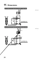
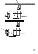
(Unit: mm)

11.2

6.7

20

3

2.8

15.5

25.4

2.4

2-M3 × 0.5 thru-hole threads

ø3.7 cable 2m long

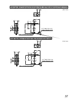
(44)

(300)

M12 connector

31

0"( &$: |;

(Unit: mm)

11.2

11.8

3.95

7.85

20

3

(2.3)

2.8

15.5

31

25.4

2-M3 × 0.5 thru-hole threads

ø3.7 cable 2m long

(44)

(300)

M12 connector

Summary of Contents for CX-400 Series

Page 1: ...2013 1 panasonic net id pidsx global Amplifier Built in Small Photoelectric Sensor CX 400 Series USER S MANUAL WUME CX400 3 ...

Page 2: ... Thru beam type CX 41 7 3 3 Mounting when detecting materials having a gloss CX 493 CX 48 9 CX 48 10 CX 44 11 12 14 5 1 Beam alignment Thru beam type CX 41 CX 49 CX 48 14 CX 42 15 8 CX 44 17 CX 44 19 21 CX 44 21 CX 491 A E F 22 9 Option 23 9 1 Slit mask Thru beam type CX 41 23 G H E CX 411 24 G CX 49 CX 48 25 JK H 26 11 Dimensions 34 ...

Page 3: ...ame raceway L Do not use during the initial transient time 50ms after the power supply is switched ON L X E E Y E E W E E E formance L UY JKK E E possible with 0 3mm2 Q A E Y power supply line and the output line of less than 10m is acceptable in case using this product as conforming to S mark L Make sure that stress by forcible bend or pulling is not applied directly to the sensor L This sensor i...

Page 4: ...switch beam thru type incorporate it in the receiver is turned fully counterclockwise D side R E E A E E opera tion mode switch slowly Turning with excessive strength will cause E Operation mode switch Stability indicator Green Lights up under the stable light condition or the stable dark condition Operation indicator Orange Lights up when the sensing output is ON Operation mode switch Operation m...

Page 5: ...ower indicator green lights up when the power is ON Operation indicator Orange Lights up when the sensing output is ON Stability indicator Green Lights up under the stable light condition or the stable dark condition ...

Page 6: ...ting to sensor mounting bracket Optional L The tightening torque should be 0 5N m or less MS CX 3 MS CX2 2 MS CX2 4 05 M3 length 12mm screw with washer Accessory of sensor mounting bracket Mounting bracket MS CX2 1 Optional ...

Page 7: ... 411 GK away CX 412 parallel deviation diagram typical Center Left Right J KKK _ 500 0 500 J KKK 5 15 L2 20 10 0 Sensing distance L m _ 7 In case using at sensing distance L2 J E _ Y 790mm according to diagram above The installation interval is Y GK j J K E CX 412 J K more away CX 413 parallel deviation diagram typical Center Left Right 4 _ 2 0 2 4 10 30 L3 40 20 0 Sensing distance L m _ 7 6 In ca...

Page 8: ...8 B B A Model No A B 10m Approx 590mm or more 15m Y J K 6 30m Approx 4 35m or more L CX 49 CX 48 fuse reflective type CX 42 CX 44 E E ...

Page 9: ... materials having a gloss 6 L Please take care of the following points when detecting materials having a gloss with ret CX 493 CX 48 1 X E A E H J 2 JK K E L X H Sensing 10 to 30 Glossy surface J E A E E E E E L E W A E F H CX 491 ...

Page 10: ...10 6 0 L AE E E E E E E E E E CX 48 L E E E E A E E E H E E L E E A E E A 8 CX 48 A CX 48 B Good Not good ...

Page 11: ... unstable operation Good Not good Good L E E X E E AE E E A X E L When a specular body is present below by tiling it slightly upwards to avoid wrong operation Tilt Specular face Specular face Not good Good L E X A E E E X E CX 44 H E A E E L Take care that there is a non detactable area right in front of CX 44 Non detavtable area CX 441 CX 443 CX 442 K CX 444 J ...

Page 12: ... E F 8 X 8 K Load 100mA max 12 to 24V DC 10 Users circuit Internal circuit Main circuit 8 A J R E L Connector pin position of the connector type 0 0 K R connected J K R connected J E E F E E E E E Load 100mA max 12 to 24V DC 10 Main circuit 8 X 8 K Users circuit Internal circuit 8 A J R E L Connector pin position of the connector type 0 0 K R connected J K R connected J ...

Page 13: ...K Users circuit Internal circuit 8 A J R E E E E Load 100mA max 8 X X R 8 K Users circuit Internal circuit 12 to 24V DC 10 Main circuit 8 A J R E L Connector pin position of the connector type 0 selection input K J R E 8 A E X 6 HJ5 KJ5 KL 7 7 HJ5 Output 0V 8 A J 8 X X selection input 8 K 7 KJ5 8 X Output 8 A J X 8 0V Output 0V ...

Page 14: ...ceiver also 5 Check that the stability indicator green lights up 6 E E E R X R W A E E A E UY Receiver U Operation indicator Orange Stability indicator Green Receiver U 1 Set the operation mode switch to the Light ON UY 2 E E E E E A E mine the range of the light received condition with E E E E E E E 3 A E E 4 E E E sensor also 5 Check that the stability indicator green lights up 6 E E E R X R W A...

Page 15: ...nge 3 E X E E clockwise until the sensor enters the Light state opera tion and then bring it back to confirm point B where the E X If the sensor does not enter the Light state operation AE E X A E B A B 4 The position at the middle of points A and B is the opti mum sensing position A B Optimum position R E E A E E A A E Y E A E ...

Page 16: ...hts up Lights up ON Stable light receiving Lights up Unstable light receiving Unstable dark receiving ON Lights up Lights up Stable dark receiving Lights up H Stability indicator Green Operation indicator Orange Output Sensing condition Lights up Lights up ON Stable dark receiving Unstable dark receiving Unstable light receiving Lights up Stable light receiving H H H H Stability indicator Green Op...

Page 17: ... H Q L E AE E E X Sensing Back ground L E E AE E E E E E E E E ON Light received at element A Light received 8 light not received Sensing in the back Setting distance Receiving element A Receiving element B U Lens Back ground L Wiring for BGS function Output 0V 8 A J 8 X X 8 K ...

Page 18: ...Received element A receives light Received element B does E Received element B receives light Conveyor or other back ground must be present Receiving U Receiving element B Conveyor Conveyor L X R L T KJ5 Output 0V 8 A J 8 X Output X 8 0V L Depends on a selection of either 8 E operation changes as follows ON ON ON ON L ON D ON BGS L ON D ON Sensing range Setting distance Non detectable ...

Page 19: ...nd Distance 2 E W E E XA H A where the sensor changes to the light received condition A 3 E E E X A B where the sensor changes to the light received condition again with only the background When the sensor does not go to the light received condition even if E XA B is this extreme point There may be more than 1 turn between the point A and B E A B 4 E E point between A and B A B Optimum position 7 ...

Page 20: ...out point A where the sensor changes to the stable dark condition A 3 E E E XA H B where the sensor changes to the stable dark condition again with only the background When the sensor does not go to the stable X E XA B is this extreme point There may be more than 1 turn between the point A and B E A B 4 E E ter point between A and B A B Optimum position ...

Page 21: ...ensors Note If CX 49 E E E E E from the opposing sensor or to detect its front face Not good Good 7 Stability Indicator of Adjustable Range L Since the CX 44 E E E E E E E E E E E A E E distance Setting distance Sensing Output operation indicator In case of L ON Stability indicator Green Stable operating condition Stable operating Unstable operating condition ON Lights up Lights up ...

Page 22: ...22 8 V E Y K L E F H may not detect an ob A H E X E A Z A H E H Gold or silver color glossy labels or wrapping paper 0 E A E E H Reduce the sensitivity E A E E ...

Page 23: ...X 413 2 7m 300mm OS CX 2 CX 411 ø2mm 2m 400mm ø12mm ø2mm CX 412 3m 600mm CX 413 6m 1 2m Rectan gular slit mask CX 411 0 5 6mm 2m 400mm ø12mm 0 5 6mm CX 412 3m 600mm CX 413 6m 1 2m OX CX 1 CX 411 1 6mm 3m 1m ø12mm 1 6mm CX 412 4 5m 1 5m CX 413 9m 3m OX CX 2 CX 411 2 6mm 5m 2m ø12mm 2 6mm CX 412 7 5m 3m CX 413 15m 6m How to mount 1 E HY E X E HY 2 E E X E E HY E HY groove Y Y Y Removing tab Slit mas...

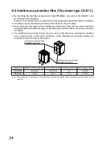
Page 24: ... E H E A E H A E H E A E H ure below L E A X E H E R E mounted on both the sets of the sensor H EK Optional H EK _ Optional Model No Direction of thru beam axis Color of the bracket Sensing distance EK Q F Light brown 5m ø12mm EK _ Vertical Silver 5m ø12mm R E R E A E H X AE E E sensors ...

Page 25: ... 481 CX 482 0 1 to 0 6m 0 3 to 0 6m ø30mm CX 483 0 1 to 0 3m 0 1 to 0 3m K Optional CX 491 1m 0 1 to 1m ø35mm j Q j 35 3mm 42 3mm 8 3mm Thru hole threads ø3 6mm CX 493 1 5m 0 1 to 1 5m CX 481 50 to 300mm 100 to 300mm CX 482 0 1 to 1 3m 0 5 to 1 3m CX 483 0 1 to 0 7m 0 2 to 0 7m tive tape K Optional CX 491 0 5m 0 1 to 0 5m ø30mm j Q j 30mm 8mm 0 7mm K E Q CX 493 0 8m 0 1 to 0 8m CX 481 CX 482 CX 48...

Page 26: ...nsistor Maximum sink current 100mA Applied voltage 30V DC or less between output and 0V Residual voltage 2V or less at 100mA sink current 1V or less at 16mA sink current E E PNP open collector transistor Maximum source current 100mA Applied voltage 30V DC or less A Residual voltage 2V or less at 100mA source current 1V or less at 16mA source current Output operation Switchable either Light ON or D...

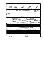
Page 27: ...plied voltage 30V DC or less between output and 0V Residual voltage 2V or less at 100mA sink current 1V or less at 16mA sink current E E PNP open collector transistor Maximum source current 100mA Applied voltage 30V DC or less A Residual voltage 2V or less at 100mA source current 1V or less at 16mA source current Output operation Switchable either Light ON or Dark ON Short circuit protection Incor...

Page 28: ...voltage 30V DC or less between output and 0V Residual voltage 2V or less at 100mA sink current 1V or less at 16mA sink current E E PNP open collector transistor Maximum source current 100mA Applied voltage 30V DC or less A Residual voltage 2V or less at 100mA source current 1V or less at 16mA source current Output operation Switchable either Light ON or Dark ON Short circuit protection Incorporate...

Page 29: ...age 12 to 24V DC 10 Ripple P P 10 or less Power consumption 20mA or less Output E NPN open collector transistor Maximum sink current 100mA Applied voltage 30V DC or less between output and 0V Residual voltage 1V or less at 100mA sink current 0 4V or less at 16mA sink current E E PNP open collector transistor Maximum source current 100mA Applied voltage 30V DC or less A Residual voltage 1V or less ...

Page 30: ...plied voltage 30V DC or less between output and 0V Residual voltage 2V or less at 100mA sink current 1V or less at 16mA sink current E E PNP open collector transistor Maximum source current 100mA Applied voltage 30V DC or less A Residual voltage 2V or less at 100mA source current 1V or less at 16mA source current Short circuit protection Incorporated Response time 1ms or less Automatic interferenc...

Page 31: ... 100mA Applied voltage 30V DC or less between output and 0V Residual voltage 2V or less at 100mA sink current 1V or less at 16mA sink current E E PNP open collector transistor Maximum source current 100mA Applied voltage 30V DC or less A Residual voltage 2V or less at 100mA source current 1V or less at 16mA source current Short circuit pro tection Incorporated Response time 1ms or less Automatic i...

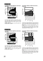
Page 32: ...typi E Q A E slight variation in the sensing range depending on the product E E E X E E E A E E A E H Correlation between lightness and sens ing range Sensing range L mm Lightness Light Dark Sensing region Distance to convergent point 80 60 40 20 0 N2 N4 N6 N8 N1 N2 N4 N3 N6 N5 N8 N9 N7 The sensing region typical is represented by oblique E Q A E should be set with enough margin because of slight ...

Page 33: ...Y E E A E HY E E E D shown on the label is the receiver Thru beam type sensor emitter Z E E R A E HY is cable length 5m type Standard 2m UY E R A E HY is cable length 0 5m type UY E R A E E HY is the sensor without the K 6 UY E A E F H E E H E F E H E E E H E K 6 E E E E F A E A E E 8 E X E A E E A B CX 491 3m 0 1 to 3m CX 493 5m 0 1 to 5m CX 481 50 to 500mm 100 to 500mm CX 483 K J KKK JKK J KKK C...

Page 34: ...6 7 20 3 2 8 15 5 25 4 2 4 2 M3 0 5 thru hole threads ø3 7 cable 2m long Cable diameter ø1 2 31 Unit mm 5 11 2 11 8 3 95 7 85 20 3 2 3 2 8 15 5 31 25 4 2 M3 0 5 thru hole threads ø3 7 cable 2m long Cable diameter ø1 2 Unit mm ...

Page 35: ...8 3 95 7 85 20 3 2 3 2 8 15 5 31 25 4 2 M3 0 5 thru hole threads ø3 7 cable 2m long Cable diameter ø1 2 4 4 Unit mm 11 2 12 5 4 8 2 20 3 0 9 2 8 2 31 25 4 2 M3 0 5 thru hole threads ø3 7 cable 2m long Cable diameter ø1 2 22 ...

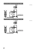
Page 36: ... 20 3 2 8 15 5 25 4 2 4 2 M3 0 5 thru hole threads ø3 7 cable 0 5m long Cable diameter ø1 2 31 Unit mm H 11 2 8 1 20 3 2 8 15 5 25 4 2 4 2 M3 0 5 thru hole threads ø3 7 cable 0 5m long Cable diameter ø1 2 31 Unit mm ...

Page 37: ... 1 20 3 2 4 2 8 15 5 31 25 4 2 M3 0 5 thru hole threads ø3 7 cable 0 5m long Cable diameter ø1 2 4 4 H Unit mm 11 2 8 1 20 3 2 4 2 8 15 5 31 25 4 2 M3 0 5 thru hole threads ø3 7 cable 0 5m long Cable diameter ø1 2 5 1 6 1 ...

Page 38: ...6 7 20 3 2 8 15 5 25 4 2 4 2 M3 0 5 thru hole threads ø3 7 cable 2m long 44 300 M12 connector 31 0 Unit mm 11 2 11 8 3 95 7 85 20 3 2 3 2 8 15 5 31 25 4 2 M3 0 5 thru hole threads ø3 7 cable 2m long 44 300 M12 connector ...

Page 39: ...1 2 11 8 3 95 7 85 20 3 2 3 2 8 15 5 31 25 4 2 M3 0 5 thru hole threads 4 4 ø3 7 cable 2m long 44 300 M12 connector 0 Unit mm 11 2 6 7 20 3 2 8 31 25 4 2 4 2 M3 0 5 thru hole threads M8 connector 15 5 35 5 42 5 ø9 4 ...

Page 40: ...11 2 11 8 3 95 7 85 20 3 2 3 2 8 15 5 31 25 4 2 M3 0 5 thru hole threads M8 connector 35 5 42 5 ø9 4 0 Unit mm 11 2 11 8 3 95 7 85 20 3 2 3 2 8 15 5 31 25 4 4 4 2 M3 0 5 thru hole threads M8 connector 35 5 42 5 ø9 4 ...

Page 41: ...41 0 Unit mm 11 2 12 5 4 8 2 20 3 0 9 2 8 2 31 25 4 22 2 M3 0 5 thru hole threads M8 connector 35 5 42 5 ø9 4 ...

Page 42: ...m 34 3 35 3 5 30 3 3 8 3 2 ø3 6 mounting hole 42 3 8 25 K Unit mm 12 8 33 3 11 3 2 25 10 2 M3 nut mounting holes for mounting at the back 2 ø3 4 thru holes for mounting at the side 2 ø3 4 thru holes 6 deep for mounting at the back 2 M3 nut mounting holes for mounting at the side ...

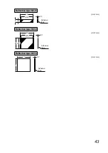
Page 43: ...43 K Unit mm 30 28 0 7 Adhesive tape 8 6 K Unit mm 30 28 0 7 25 23 Adhesive tape K 6 Unit mm 30 0 7 Adhesive tape 30 ...

Page 44: ...gai shi Aichi 486 0901 Japan ƛ Telephone 81 568 33 7861 ƛ Facsimile 81 568 33 8591 panasonic net id pidsx global About our sale network please visit our website Panasonic Industrial Devices SUNX Co Ltd 2013 January 2013 PRINTED IN JAPAN WUME CX400 3 Please contact ...

Reviews: