background image

144 

18.1.5  CS-XE24WKUAW  CU-XE24WKUA 

Rated frequency (compressor speed is fixed during forced heating or cooling for capacity measurement and 
diagnosis purpose) 
 

Indoor (°C / °F) 

Outdoor (°C / °F) 

DB 

WB 

-20 (-4.0) 

-10 (14.0) 

0 (32.0) 

5 (41.0) 

TC 

SHC 

IP 

TC 

SHC 

IP 

TC 

SHC 

IP 

TC 

SHC 

IP 

27 

(80.6) 

19 (66.2)  29537 

24727 

1583 

29508 

24702 

1564 

29471 

25145 

1517 

29389 

24589 

1504 

22 (71.6)  33883 

20211 

1383 

33849 

20191 

1366 

32267 

19752 

1584 

30096 

18519 

1580 

23 

(73.4) 

16 (60.8)  25994 

25734 

1746 

25968 

25708 

1725 

27606 

27330 

1436 

26318 

26055 

1592 

18 (64.4)  29060 

19023 

1599 

29031 

19004 

1579 

32347 

21043 

1250 

30137 

17932 

1662 

20 

(68.0) 

13 (55.4)  22882 

22653 

1733 

22859 

22631 

1711 

22712 

22485 

1137 

21891 

21672 

1359 

16 (60.8) 

2876 

2000 

2000 

2876 

2000 

1976 

2876 

2000 

1182 

2876 

2000 

1167 


Indoor (°C / °F) 

Outdoor (°C / °F) 

DB 

WB 

16 (60.8) 

25 (77.0) 

35 (95.0) 

46 (114.8) 

TC 

SHC 

IP 

TC 

SHC 

IP 

TC 

SHC 

IP 

TC 

SHC 

IP 

27 

(80.6) 

19 (66.2)  29275 

24910 

1483 

25617 

22148 

2022 

23973 

22055 

2200 

16455 

15139 

1978 

22 (71.6)  30286 

19813 

1488 

27857 

17528 

2044 

26454 

13778 

2229 

18158 

9457 

2004 

23 

(73.4) 

16 (60.8)  27145 

26874 

1483 

23702 

23465 

1983 

21938 

21719 

2323 

15058 

14908 

2088 

18 (64.4)  29627 

18928 

1487 

26054 

16870 

2005 

24151 

16362 

2365 

16577 

11231 

2127 

20 

(68.0) 

13 (55.4)  23731 

23493 

1241 

22199 

21977 

1982 

20229 

20027 

2282 

13885 

13746 

2052 

16 (60.8) 

2876 

2000 

2012 

2876 

2000 

2544 

2876 

2000 

2486 

2876 

2000 

2235 


Summary of Contents for CS-XE9WKUAW

Page 1: ...nicians Any attempt to service or repair the products dealt with in this service information by anyone else could result in serious injury or death PRECAUTION OF LOW TEMPERATURE In order to avoid fros...

Page 2: ...de Cooling area of Dry Mode 70 13 6 Powerful Mode Operation 70 13 7 Timer Control 70 13 8 Auto Restart Control 71 13 9 Indication Panel 71 13 10 Room Freeze Protection Function RFP Operation 71 13 11...

Page 3: ...in the refrigerant cycle piping and possibly result in explosion and injury For R32 and R410A the same flare nut on the outdoor unit side and pipe can be used Since the working pressure for R32 R410A...

Page 4: ...l shock in case of equipment breakdown or insulation breakdown CAUTION 1 Do not install the unit at place where leakage of flammable gas may occur In case gas leaks and accumulates at surrounding of t...

Page 5: ...l dB 58 58 Outdoor Noise H L QLo dB A 48 48 Power Level dB 63 63 Heating Capacity kW 0 89 3 21 5 29 0 89 3 21 5 29 BTU h 3000 10900 18000 3000 10900 18000 Running Current A 3 60 3 20 Input Power W 150...

Page 6: ...710 Min Circuit Ampacity 15 00 Max Overcurrent Protection 15 00 SEER HSPF 28 20 14 50 Moisture Removal L h Pt h 0 6 1 3 Indoor Airflow QLo Cool m min ft min 4 46 157 Heat m min ft min 6 43 227 Lo Coo...

Page 7: ...lypropelene Type One touch Power Supply Outdoor Power Supply Cord Nil Thermostat Electronic Control Protection Device Electronic Control Dry Bulb Wet Bulb Indoor Operation Range Cooling Maximum F C 89...

Page 8: ...1 61 Outdoor Noise H L QLo dB A 49 49 Power Level dB 64 64 Heating Capacity kW 0 89 3 51 6 72 0 89 3 51 6 72 BTU h 3000 12000 23000 3000 12000 23000 Running Current A 4 20 3 80 Input Power W 150 800 1...

Page 9: ...m 890 Min Circuit Ampacity 15 00 Max Overcurrent Protection 20 00 SEER HSPF 24 60 13 00 Moisture Removal L h Pt h 1 2 2 5 Indoor Airflow QLo Cool m min ft min 4 48 158 Heat m min ft min 7 76 274 Lo Co...

Page 10: ...Polypropelene Type One touch Power Supply Outdoor Power Supply Cord Nil Thermostat Electronic Control Protection Device Electronic Control Dry Bulb Wet Bulb Indoor Operation Range Cooling Maximum F C...

Page 11: ...61 61 Outdoor Noise H L QLo dB A 51 51 Power Level dB 66 66 Heating Capacity kW 0 98 5 04 7 03 0 98 5 04 7 03 BTU h 3300 17200 24000 3300 17200 24000 Running Current A 6 60 5 80 Input Power W 200 1 26...

Page 12: ...m 660 Min Circuit Ampacity 20 00 Max Overcurrent Protection 25 00 SEER HSPF 21 10 12 00 Moisture Removal L h Pt h 1 9 4 0 Indoor Airflow QLo Cool m min ft min 8 16 288 Heat m min ft min 8 47 299 Lo Co...

Page 13: ...olypropelene Type One touch Power Supply Outdoor Power Supply Cord Nil Thermostat Electronic Control Protection Device Electronic Control Dry Bulb Wet Bulb Indoor Operation Range Cooling Maximum F C 8...

Page 14: ...63 Outdoor Noise H L QLo dB A 52 52 Power Level dB 66 66 Heating Capacity kW 1 70 5 97 8 79 1 70 5 97 8 79 BTU h 5800 20400 30000 5800 20400 30000 Running Current A 8 70 7 70 Input Power W 380 1 63k...

Page 15: ...m 580 Min Circuit Ampacity 20 00 Max Overcurrent Protection 25 00 SEER HSPF 21 00 12 00 Moisture Removal L h Pt h 1 7 3 6 Indoor Airflow QLo Cool m min ft min 10 89 384 Heat m min ft min 10 92 386 Lo...

Page 16: ...Polypropelene Type One touch Power Supply Outdoor Power Supply Cord Nil Thermostat Electronic Control Protection Device Electronic Control Dry Bulb Wet Bulb Indoor Operation Range Cooling Maximum F C...

Page 17: ...65 Outdoor Noise H L QLo dB A 53 53 Power Level dB 67 67 Heating Capacity kW 1 70 8 46 9 90 1 70 8 46 9 90 BTU h 5800 28800 33800 5800 28800 33800 Running Current A 12 80 11 50 Input Power W 380 2 52k...

Page 18: ...m 710 Min Circuit Ampacity 25 00 Max Overcurrent Protection 30 00 SEER HSPF 20 00 10 60 Moisture Removal L h Pt h 3 6 7 6 Indoor Airflow QLo Cool m min ft min 11 28 398 Heat m min ft min 10 86 383 Lo...

Page 19: ...Polypropelene Type One touch Power Supply Outdoor Power Supply Cord Nil Thermostat Electronic Control Protection Device Electronic Control Dry Bulb Wet Bulb Indoor Operation Range Cooling Maximum F C...

Page 20: ...ner protector to protect compressor o Noise prevention during soft dry operation Operation Improvement o Quiet mode to reduce the indoor unit operating sound o Powerful mode to reach the desired room...

Page 21: ...ction louver Do not adjust by hand Vertical airflow direction louver Do not adjust by hand Remote Control Receiver Distances 26ft 8m INDICATOR Aluminium fin Auto OFF ON button Use when remote control...

Page 22: ...AIR SWING TEMP POWERFUL FAN SPEED QUIET OFF ON LCD display Powerful operation Operation mode Fan speed selection Quiet operation Transmitter OFF ON Airflow direction adjustment nanoeX operation RFP op...

Page 23: ...2 13 32 41 61 4 3 16 105 8 4 11 16 119 1 2 3 8 60 2 3 8 60 1 21 32 41 5 11 5 8 295 2 3 8 60 3 32 1 32 2 0 5 3 32 1 32 2 0 5 1 32 1 32 0 5 0 5 1 32 1 32 0 5 0 5 Top View Front View Bottom View Rear Vi...

Page 24: ...2 17 32 64 Remote Control Holder Remote Control 5 11 16 144 5 2 5 16 59 7 8 22 MODE AIR SWING TEMP MODE RFP RFP AIR SWING TEMP POWERFUL FANSPEED QUIET OFF ON 9 5 8 244 43 13 32 1102 5 5 16 135 5 5 16...

Page 25: ...24 1 2 622 3 27 32 97 6 19 32 167 13 330 2 way valve at Liquid side High Pressure 3 way valve at Gas side Low Pressure Unit inch mm Unit inch mm Side View Front View Top View Side View 34 15 32 875 1...

Page 26: ...8 1000 3 15 16 100 Side View Front View Top View Side View 2 way valve at Liquid side High Pressure 3 way valve at Gas side Low Pressure Unit inch mm 34 15 32 875 12 5 8 320 2 11 32 59 1 3 32 27 5 24...

Page 27: ...AKE AIR TEMP SENSOR PIPE TEMP SENSOR 1 PIPE TEMP SENSOR 2 PIPE TEMP SENSOR AIR TEMP SENSOR LIQUID SIDE 2 WAY VALVE 3 WAY VALVE GAS SIDE COOLING HEAT EXCHANGER EVAPORATOR HEATING COMPRESSOR HEAT EXCHAN...

Page 28: ...E TEMP SENSOR 1 PIPE TEMP SENSOR 2 PIPE TEMP SENSOR AIR TEMP SENSOR LIQUID SIDE 2 WAY VALVE 3 WAY VALVE GAS SIDE COOLING HEAT EXCHANGER EVAPORATOR HEATING COMPRESSOR HEAT EXCHANGER CONDENSER PROCESS T...

Page 29: ...NSOR PIPE TEMP SENSOR 1 PIPE TEMP SENSOR 2 PIPE TEMP SENSOR AIR TEMP SENSOR LIQUID SIDE 2 WAY VALVE 3 WAY VALVE GAS SIDE COOLING HEAT EXCHANGER EVAPORATOR HEATING COMPRESSOR HEAT EXCHANGER CONDENSER P...

Page 30: ...30 7 Block Diagram 7 1 CS XE9WKUAW CU XE9WKUA CS XE12WKUAW CU XE12WKUA FUSE 301 SC TEMPERATURE FUSE L1 L2 SINGLE PHASE POWER SUPPLY 1 208 230V 60Hz INDOOR UNIT OUTDOOR UNIT 1 2 3 M...

Page 31: ...31 7 2 CS XE15WKUAW CU XE15WKUA CS XE18WKUAW CU XE18WKUA CS XE24WKUAW CU XE24WKUA FUSE 301 SC TEMPERATURE FUSE U L1 L2 SINGLE PHASE POWER SUPPLY 1 208 230V 60Hz INDOOR UNIT OUTDOOR UNIT 2 3 M 1...

Page 32: ...W B Y R RECTIFICATION CIRCUIT COMMUNICATION CIRCUIT FUSE301 T3 15A L250V NOISE FILTER CIRCUIT G ELECTRONIC CONTROLLER MAIN 6 1 2 1 CN TH RED CN HT WHT t t t PIPING TEMP SENSOR 2 THERMISTOR PIPING TEM...

Page 33: ...LOW W WHITE G GREEN GR GRAY R RED Y G YELLOW GREEN 1 2 3 CN STM1 WHT CN STM2 YLW CN CNT WHT GR W BR G Y 5 1 5 1 UP DOWN LOUVER MOTOR OUTER LEFT RIGHT LOUVER MOTOR CN STM3 BLU BR R O Y P 1 5 1 M 5 BR R...

Page 34: ...CUIT FUSE 1 20A 250V FUSE 6 20A 250V FUSE 8 T3 15A L250V FUSE 3 T3 15A L250V FUSE 5 20A 250V FAN MOTOR GRN GRN 1 L2 L1 2 3 TERMINAL BOARD YELLOW YLW TRADEMARK COMPRESSOR TERMINAL THE PARENTHESIZED LET...

Page 35: ...LU 1 1 1 3 3 1 1 1 6 ELECTRO MAGNETIC COIL EXPANSION VALVE ELECTRO MAGNETIC COIL 4 WAY VALVE COMP TEMP SENSOR THERMISTOR OUTDOOR AIR TEMP SENSOR THERMISTOR 4 3 t t t 7 MS 3 M M V W U V W REMARKS BLU B...

Page 36: ...AGNETIC COIL EXPANSION VALVE ELECTRO MAGNETIC COIL 4 WAY VALVE COMP TEMP SENSOR THERMISTOR OUTDOOR AIR TEMP SENSOR THERMISTOR 4 3 t t t 7 MS 3 M M V W U V W REMARKS BLU BLUE BLK BLACK WHT WHITE RED RE...

Page 37: ...STOR SUCTION TEMP SENSOR THERMISTOR 1 2 3 CN STM1 WHT CN STM2 YLW CN CNT WHT GR W BR G Y 5 1 5 1 UP DOWN LOUVER MOTOR OUTER LEFT RIGHT LOUVER MOTOR CN STM3 BLU BR R O Y P 1 5 1 M 5 BR R O Y P 1 5 1 M...

Page 38: ...V YLW CN DISP YLW 4 W W W W W W W W W 1 8 ELECTRONIC CONTROLLER RECEIVER DISPLAY SW01 C52 1000p 50V C56 L5 5V L6 12V C51 1000p 50V F301 R90 10k R82 10k 5V 12V 1 2 3 4 5 6 7 16 15 14 13 12 11 10 IC06 1...

Page 39: ...4 1 3 1 6 P N Q1 OUTDOOR AIR TEMP SENSOR THERMISTOR PIPING TEMP SENSOR THERMISTOR COMPRESSOR TEMP SENSOR THERMISTOR CN HOT WHT 1 3 YLW YLW ELECTRO MAGNETIC COIL 4 WAY VALVE ELECTRO MAGNETIC COIL EXPA...

Page 40: ...IT ELECTRONIC CONTROLLER FAN MOTOR BLU PFC CIRCUIT RECTIFICATION CIRCUIT SWITCHING POWER SUPPLY CIRCUIT RECTIFICATION CIRCUIT PIPING TEMP SENSOR THERMISTOR GROUNDING TERMINAL RY HOT CABINET SIDE PLATE...

Page 41: ...YEL YEL WHT BLK COMPRESSOR CN TH1 WHT CN TANK WHT CN EV WHT CN HOT BLU 1 1 1 3 3 1 1 1 6 ELECTRO MAGNETIC COIL EXPANSION VALVE ELECTRO MAGNETIC COIL 4 WAY VALVE COMP TEMP SENSOR THERMISTOR OUTDOOR AI...

Page 42: ...d 10 1 Indoor Unit 10 1 1 Main Printed Circuit Board 10 1 1 1 CS XE9WKUAW CS XE12WKUAW CS XE15WKUAW CN TH CN CNT CN FM CN HT CN STM2 CN NANO CN STM1 CN STM3 CN RMT CN RCV CN DISP CN WLAN JP1 Random Au...

Page 43: ...43 10 1 1 2 CS XE18WKUAW CS XE24WKUAW CN FM CN CNT CN STM2 CN DATA1 CN STM3 CN STM1 CN RMT CN TH CN DATA3 CN DISP CN RCV CN HT JP1 Random Auto Restart enable disable...

Page 44: ...10 1 2 2 CS XE18WKUAW CS XE24WKUAW 10 1 3 Receiver Printed Circuit Board CS XE9WKUAW CS XE12WKUAW CS XE15WKUAW 10 1 4 Sub Printed Board CS XE18 24WKUAW LED201 LED202 LED203 LED204 LED205 LED206 CN DIS...

Page 45: ...45 10 1 5 Nanoe X Printed Circuit Board...

Page 46: ...46 10 2 Outdoor Unit 10 2 1 Main Printed Circuit Board 10 2 1 1 CU XE9WKUA CU XE12WKUA POWER TRANSISTOR IPM CN MTR1 CN STM1 CN TH1 AC WHT AC BLK CN TANK CN HOT...

Page 47: ...47 10 2 2 CU XE15WKUA CU XE18WKUA CU XE24WKUA CN DCFM CN HOT CN TANK CN EV CN TH1 AC BLK AC WHT POWER TRANSISTOR IPM CURRENT TRANSFORMER CT...

Page 48: ...ft 10 m distance the quantity of additional refrigerant should be 1 64 oz 37 5 g 32 8 24 6 ft x 0 2 oz ft 1 64 oz 10 7 5 m x 15 g m 37 5 g 11 1 3 Indoor Outdoor Unit Installation Diagram Model Capaci...

Page 49: ...llation plate The meeting point of the extended line is the center of the hole Another method is by putting measuring tape at position as shown in the diagram above The hole center is obtained by meas...

Page 50: ...as mentioned in indoor outdoor unit installation Install the Indoor Unit Secure the Indoor Unit Insulate and finish the piping Step 1 Pull the connection cable into Indoor Unit Step 3 Cut and flare th...

Page 51: ...inserted to drain hose adapter 7 Sleeve for piping hole Drain hose Piping Connection cable More than 37 13 32 950 mm For right piping follow the same procedure Cable 45 Drain hose Piping PVC tube for...

Page 52: ...reen Y G in colour and shall be longer than other lead wires as shown in the figure for electrical safety in case of slipping 11 2 3 1 Wire Stripping and Connecting Requirement Terminals on the indoor...

Page 53: ...sufficiently tighten the flare nut with fingers Further tighten the flare nut with torque wrench in specified torque as stated in the table 11 3 2 2 Connecting the Piping to Outdoor Decide piping len...

Page 54: ...repair location of leak Do not release refrigerant during piping work for installation and reinstallation Be careful with the liquid refrigerant it may cause frostbite 11 3 4 Connect the Cable to the...

Page 55: ...o instruction 11 2 3 of indoor unit WARNING This equipment must be properly earthed Earth lead wire shall be Yellow Green Y G in colour and should be longer than other lead wires as shown in the figur...

Page 56: ...pe local supply to dispose drained water from the elbow or use a stainless steel tray local supplied to collect and dispose water If the unit is used in an area where temperature falls below 32 F 0 C...

Page 57: ...lled at 41 ft 12 5 m distance the quantity of additional refrigerant should be 1 64 oz 50 g 41 32 8 ft x 0 2 oz ft 1 64 oz 12 5 10 m x 20 g m 50 g 12 1 3 Indoor Outdoor Unit Installation Diagram Model...

Page 58: ...plate The meeting point of the extended line is the center of the hole Another method is by putting measuring tape at position as shown in the diagram above The hole center is obtained by measuring t...

Page 59: ...tioned in indoor outdoor unit installation Install the Indoor Unit Secure the Indoor Unit Insulate and finish the piping Step 1 Pull the connection cable into Indoor Unit Step 3 Cut and flare the embe...

Page 60: ...dure Drain cap Drain hose Sleeve for piping hole Drain hose Piping Connection cable More than 45 9 32 1150 mm 80mm T HOLE C P H C PVC tube for drain hose Indoor unit 3 7 32 82 mm Piping Cable Apply pu...

Page 61: ...reen Y G in colour and shall be longer than other lead wires as shown in the figure for electrical safety in case of slipping 12 2 3 1 Wire Stripping and Connecting Requirement Terminals on the indoor...

Page 62: ...nut with fingers Further tighten the flare nut with torque wrench in specified torque as stated in the table 12 3 2 2 Connecting the Piping to Outdoor Decide piping length and then cut by using pipe...

Page 63: ...nstallation and reinstallation Be careful with the liquid refrigerant it may cause frostbite 12 3 4 Connect the Cable to the Outdoor Unit 1 Remove control board cover Resin and Metal 2 Remove particul...

Page 64: ...25 32 20mm diameter holes with Rubber caps refer to illustration below o Use a rigid or flexible PVC pipe local supply to dispose drained water from the elbow or use a stainless steel tray local suppl...

Page 65: ...stat control Compressor is OFF when Intake Air Temperature Internal Setting Temperature 2 7 F 1 5 C continue for 3 minutes When compressor is OFF Thermostat OFF and AUTO FAN is set the fan will stop p...

Page 66: ...e then continue in DRY mode otherwise COOL mode is decided o If 3 6 F 2 C indoor intake temperature remote control setting temperature 5 4 F 3 C maintain with previous mode o If indoor intake temperat...

Page 67: ...r error counter increase fan motor is then stop and restart If the fan motor counter becomes 7 times then H19 fan motor error is detected Operation stops and cannot on back 13 3 Outdoor Fan Motor Oper...

Page 68: ...5 Cooling and Fan Auto 65 115 58 100 Manual 65 67 94 100 115 58 63 70 80 100 Soft Dry Auto 65 115 58 100 Manual 65 67 94 100 115 58 63 70 80 100 1 Automatic vertical airflow direction can be set using...

Page 69: ...epends on the indoor heat exchanger temperature as Figure 1 below It does not swing during fan motor stop When the air conditioner is stopped using remote control the vane will shift to close position...

Page 70: ...y until QUIET will be shown on remote control display o Quiet operation stop condition POWERFUL button is pressed Stop by OFF ON switch Timer OFF activates When FAN SPEED QUIET button is pressed again...

Page 71: ...ation OFF Timer Setting OFF RFP OFF OFF OFF Note If POWER LED is blinking the possible operation of the unit are Hot Start during Deice operation operation mode judgment or ON timer sampling If Timer...

Page 72: ...disabled when fan speed 360 rpm o During nanoe X individual operation fan speed follow remote control setting Auto Fan Speed for nanoe X individual operation is cooling medium fan Powerful Quiet is d...

Page 73: ...isconnection abnormality will judged when disconnection counter 3 Abnormal code H67 will memorized in EEPROM and nanoe X LED OFF Timer LED not blinking Disconnection counters clear condition Disconnec...

Page 74: ...the frequency bands Type of wireless Frequency band Max EIRP dBm WLAN 12 2472 MHz 20 dBm 13 12 2 Connecting Network Press to communicate with the home wireless LAN access point Wireless LAN LED blink...

Page 75: ...on When module and ID micon CN LAN communication is following below condition o No response against sending data o Reply error against sending data o Regularly sending from AC unit Every 1 minutes Eit...

Page 76: ...e than or same as 4 C Heater ON Intake air temperature control Evaporator pipe sensor control Indoor Fan speed more than or same as Lo Fan Control content o Electric heater will be switch ON when all...

Page 77: ...Control Specification o Power 100 W o Voltage 230 V Purpose o To control base pan heater cable operation to melt ice on base pan during heating operation Starting conditions o When outdoor air temper...

Page 78: ...A 12 47 A Heat X 7 42 A 9 05 A 11 73 A 11 65 A 15 25 A Y 14 57 A 14 57 A 14 67 A 19 00 A 19 00 A 4 The first 30 minutes of cooling operation A will be applied 14 1 3 IPM Power transistor Prevention Co...

Page 79: ...onditions above happen 2 times within 20 minutes the unit will Stop operation Timer LED blinks and F91 indicated 14 1 6 Low Frequency Protection Control 1 When the compressor operate at frequency lowe...

Page 80: ...e Prevention Control 1 When indoor heat exchanger temperature is lower than 32 F 0 C continuously for 6 minutes compressor will stop operating Compressor will resume its operation 3 minutes after the...

Page 81: ...2 Compressor ON Compressor OFF The indoor unit fan stops for 90 seconds and then blows at minimum airflow for 20 seconds 14 3 Protection Control For Heating Operation 14 3 1 Intake Air Temperature Con...

Page 82: ...ture is low cold draught operation starts where indoor fan speed will be reduced 14 3 6 Deice Operation When outdoor pipe temperature and outdoor air temperature is low deice operation start where ind...

Page 83: ...e is in standby condition and press AC RESET button and then press any button at remote control to transmit and store the desired transmission code to the EEPROM There are 4 types of remote control tr...

Page 84: ...t will run Cooling or DRY operation After 30s sampling the unit will judge the operation mode base on remote controller temperature setting and Indoor Intake Sensor New Auto Mode or Outdoor Intake Sen...

Page 85: ...n o Press TEMP increment or decrement button to choose No 5 o Press Timer increment or decrement button to select desired temperature low limit of set temperature for HEAT mode o Press Timer Set butto...

Page 86: ...ring electric current during operation Measuring gas side pressure Excessive amount of refrigerant Inefficient compressor Insufficient refrigerant Insufficient refrigerant Inefficient compressor Clogg...

Page 87: ...Electric current during operation Low Pressure High Pressure Electric current during operation Insufficient refrigerant gas leakage Clogged capillary tube or Strainer Short circuit in the indoor unit...

Page 88: ...e controller continuously for 5 seconds 3 will be displayed on the remote controller display Note Display only for No transmitting signal no receiving sound and no Power LED blinking 4 Press the TIMER...

Page 89: ...d wire and connector H28 Outdoor heat exchanger temperature sensor 1 abnormality Continuous for 5s Outdoor heat exchanger temperature sensor 1 open or short circuit Outdoor heat exchanger temperature...

Page 90: ...door PCB faulty F91 Refrigeration cycle abnormality 2 times happen within 20 minutes Refrigeration cycle abnormal Insufficient refrigerant or valve close F93 Compressor abnormal revolution 4 times hap...

Page 91: ...ponent AC power supply abnormal fluctuation Defect in communication circuitry of outdoor unit PCB Replace the PCB Improper connection at terminals indoor outdoor Check indoor outdoor connecting cable...

Page 92: ...indoor and outdoor units Troubleshooting When abnormality indication starts again For safety reason and to prevent component breakdown always switch off the power before remove and connect the compone...

Page 93: ...always switch off the power before remove and connect the component Connector poor contact Correct the connection Defect in outdoor unit PCB Replace the outdoor unit PCB Defect in indoor intake air t...

Page 94: ...tion Defect in outdoor compressor temperature sensor Replace the outdoor compressor temperature sensor Defect in outdoor unit PCB Replace the outdoor unit PCB Turn off the power Check the connector co...

Page 95: ...tion pressure and running current is normal Running current is much too low and suction pressure is much too high In forced cooling check suction pressure versus running current Running current and su...

Page 96: ...en abnormality indication starts again Replace fan motor Does fan rotate smoothly Turn power supply on and operate fan Does it rotate Stop fan motor Check the rotation feedback output from fan motor R...

Page 97: ...connection Defect in outdoor unit PCB Replace the outdoor unit PCB Defect in outdoor intake air temperature sensor Replace the outdoor air temperature sensor NO NO YES YES Check the connector connecti...

Page 98: ...ndication starts again For safety reason and to prevent component breakdown always switch off the power before remove and connect the component Turn off the power Check the connector connection Defect...

Page 99: ...prevent component breakdown always switch off the power before remove and connect the component No No YES YES Check the outdoor heat exchanger temperature sensor Plug out connector from the outdoor u...

Page 100: ...remove and connect the component Is the measured resistance of the outdoor discharge pipe temperature sensor matches the value specified in its characteristic chart Is the connector connection normal...

Page 101: ...e remove and connect the component Is the measured resistance of the outdoor heat exchanger temperature sensor matches the value specified in its characteristic chart Is the connector connection norma...

Page 102: ...Troubleshooting When abnormality indication starts again For safety reason and to prevent component breakdown always switch off the power before remove and connect the component Match the compatible...

Page 103: ...nd connect the component Is the measured resistance of the outdoor gas pipe temperature sensor matches the value specified in its characteristic chart Is the connector connection normal YES YES Check...

Page 104: ...remove and connect the component Is the measured resistance of the outdoor liquid pipe temperature sensor matches the value specified in its characteristic chart Is the connector connection normal YES...

Page 105: ...t Caution Does fan rotate smoothly Turn off power supply and rotate fan by hand Does it rotate YES NO YES Turn off power supply and disconnect fan motor CN MRT2 Check resistance of the motor Measure a...

Page 106: ...lity indication starts again Replace fan motor Does fan rotate smoothly Turn power supply on and operate fan Does it rotate Stop fan motor Check the rotation feedback output from fan motor Rotate the...

Page 107: ...kdown always switch off the power before remove and connect the component Clean the air filter Is the air filter dirty Check the dust accumulation on the indoor unit heat exchanger Is the indoor unit...

Page 108: ...on and to prevent component breakdown always switch off the power before remove and connect the component Is there any short circuit Check the indoor unit air filter Is the air filter dirty Check the...

Page 109: ...hermistor matches the value specified in its characteristic chart The 4 way valve may have been damaged or wrongly connected between discharge and suction tube Problem occurs in heating mode only Is 4...

Page 110: ...ty sensor Faulty expansion valve Troubleshooting When F17 indication happens For safety reason and to prevent component breakdown always switch off the power before remove and connect the component Ch...

Page 111: ...itch off the power before remove and connect the component Replace the outdoor unit PCB Defect in PFC circuitry Replace outdoor fan motor Defect in outdoor fan motor Replace compressor Defect in compr...

Page 112: ...1 indication happens For safety reason and to prevent component breakdown always switch off the power before remove and connect the component Check for gas leaking source Repair or replace defected pa...

Page 113: ...ove and connect the component YES YES NO NO Connector poor contact Correct the connection IPM defective Replace compressor Replace outdoor unit PCB Check the U V and W connector connection Turn OFF th...

Page 114: ...the connector of outdoor heat exhanger thermistor from the PCB Measure the resistance of the outdoor heat exchanger thermistor Is there any improper heat radiation Is the outdoor fan motor operating...

Page 115: ...IPM overheats due to defective of outdoor fan motor IPM overheats due to defective of internal circuitry of IPM IPM overheats due to defective IPM temperature sensor Multi Models Only o Compressor OL...

Page 116: ...fore remove and connect the component Replace the compressor tank temperature sensor Repair the pipe flare or union nuts Reclaim and recharge refrigerant Open the 2 3 way valve Replace expansion valve...

Page 117: ...ing For safety reason and to prevent component breakdown always switch off the power before remove and connect the component Replace the outdoor unit PCB Repair the pipe flare or union nuts Reclaim an...

Page 118: ...eplace the outdoor unit PCB Compressor defective due to mechanical locked Replace compressor Compressor defective due to winding shorted Replace compressor Amplification IC defect Diode defect Defect...

Page 119: ...ntal Vane and Front Grille Figure 1 Figure 2 1 Lift to open horizontal vane gently 3 Remove the 2 caps and 2 screws on the front frille 2 Slide the lever from locked position into release position and...

Page 120: ...ire Black terminal wire White terminal wire Red and earth wire Green 9 Pull out the electronic controller halfway 8 Remove screw to remove terminal board complete 7 Remove the indicator complete then...

Page 121: ...and pull out the HVU unit 12 Remove the network adapter box by releasing the hook HVU unit Network adapter 13 Pull out and remove the drain hose from the discharge grille 14 Then pull the discharge g...

Page 122: ...122 17 1 1 5 To Remove Cross Flow Fan and Indoor Fan Motor Figure 9 Figure 10 Figure 11...

Page 123: ...123 Figure 12...

Page 124: ...re 1 17 2 1 2 To Remove Electronic Controllers Figure 2 Figure 3 2 Remove 3 caps and 4 screws at the bottom of discharge vane and 1 screw at the front grille 1 Lift to open the horizontal vane gently...

Page 125: ...N NANO CN 101 CN WLAN CN 103 9 Detach all connectors from main electronic controller and sub 10 Remove the screw and pull out the HVU unit 11 Remove Wireless LAN Module by releasing the hook HVU unit...

Page 126: ...Indoor Fan Motor Figure 9 Figure 10 14 Remove the 4 screws holding the control board then pull out the control board 15 Remove the screw that holding the cross flow fan and fan motor axis 17 Remove th...

Page 127: ...or please adjust the connector to 45 with fan motor before fixing control board 19 Remove the cross flow fan from the unit by pulling it to the left and downward 18 Push the holdfast to the left and l...

Page 128: ...move the cover by unclipping it and pulling it out 3 Remove the top casing by pressing the side of the network adapter box 4 After that network adapter can be easily replaced Reminder Serviceman or ow...

Page 129: ...ctronic controller be careful of electrostatic discharge 1 Remove the 5 screws of the Top Panel Fig 1 2 Remove the 8 screws of the Front Panel Fig 2 3 Remove the screw of the Terminal Board Cover 4 Re...

Page 130: ...the Top Cover of the Electronic Controller Fig 3 4 Remove the Control Board Fig 4 5 Remove the 8 screws of the Electronic Controller Fig 5 Caution When handling electronic controller be careful of ele...

Page 131: ...emove the 4 screws of the Top Panel Fig 1 2 Remove the 10 screws of the Front Panel Fig 2 3 Remove the Top Cover of the Electronic Controller Fig 3 4 Remove the Control Board Fig 4 5 Remove the 8 scre...

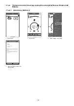
Page 132: ...ytimer Quiet Living room Menu User list Owner Change password Replace device Changerouter settings Device list Group list Application settings User s manual Terms of use Copyright Logout 1 Select air...

Page 133: ...d connection setup mode 3 Select the preferred router support connectivity mode ConnectionGuide Step1 Step2 Step3 Connect with WPS mode Connect with AP mode The router supports WPS The router does not...

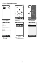
Page 134: ...di oner and press SET bu on once 4 A er step 1 3 havebeen done tap Next Connection Guide Step 1 Step 2 Step 3 Cancel Next S E T CAN CEL Allow Comfort Cloud If Wireless LAN LED is OFF during the connec...

Page 135: ...the Wireless LAN LED is ON tap Next If the Wireless LAN LED is ON tap Next Cancel Check Connection Guide Step 1 Step 2 Step 3 When the connec on of air condi oner torouter is successful the Wireless L...

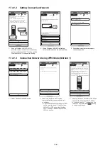
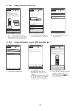
Page 136: ...rd Device password setting Step1 Step2 Step3 Cancel Registe r 1 Select the air conditioner model to register the device 2 Once connection is establish between the app and the new air conditioner throu...

Page 137: ...use 22 23 16 May 15 50 27 0 C SET Cool Statisti c Weeklytimer Quiet Living room Menu User list Owner Change password Replace device Change router settings Device list Group list Application settings U...

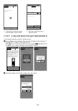
Page 138: ...ngs Device list Group list Application settings User s manual Terms of use Copyright Logout 1 Select air conditioner 2 Select e c i v e d e c a l p e R t c e l e S 3 u n e M My Home Living Room CS HZ2...

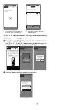
Page 139: ...d connection setup mode 3 Select the preferred router support connectivity mode ConnectionGuide Step1 Step2 Step3 Connect with WPS mode Connect with AP mode The router supports WPS The router does not...

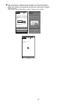
Page 140: ...di oner and press SET bu on once 4 A er step 1 3 havebeen done tap Next Connection Guide Step 1 Step 2 Step 3 Cancel Next S E T CAN CEL Allow Comfort Cloud If Wireless LAN LED is OFF during the connec...

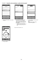
Page 141: ...x e N t x e N If the Wireless LAN LED is ON tap Next Connection Guide Step 1 Step 2 Step 3 When the connec on of air condi oner torouter is successful the Wireless LAN LEDchanges from blinking toON I...

Page 142: ...4 4 9975 6464 393 9262 5903 495 8232 5929 540 5685 3623 200 20 68 0 13 55 4 6989 6919 180 6862 6794 385 7374 7300 549 3998 3958 155 16 60 8 2876 2000 347 2876 2000 507 2876 2000 544 2876 2000 204 18 1...

Page 143: ...214 8434 8349 1089 16 60 8 2876 2000 1070 2876 2000 1353 2876 2000 1322 2876 2000 1436 18 1 4 CS XE18WKUAW CU XE18WKUA Rated frequency compressor speed is fixed during forced heating or cooling for ca...

Page 144: ...043 1250 30137 17932 1662 20 68 0 13 55 4 22882 22653 1733 22859 22631 1711 22712 22485 1137 21891 21672 1359 16 60 8 2876 2000 2000 2876 2000 1976 2876 2000 1182 2876 2000 1167 Indoor C F Outdoor C F...

Page 145: ...864 5503 5448 244 16 60 8 11030 8709 546 11355 8506 798 10316 8018 856 6970 4880 322 18 1 7 CS XE12WKUAW CU XE12WKUA Maximum Capacity Indoor C F Outdoor C F DB WB 20 4 0 10 14 0 0 32 0 5 41 0 TC SHC I...

Page 146: ...0925 10815 1832 16 60 8 19848 13988 1591 19630 13986 1997 17929 7446 2147 13836 11458 2005 18 1 9 CS XE18WKUAW CU XE18WKUA Maximum Capacity Indoor C F Outdoor C F DB WB 20 4 0 10 14 0 0 32 0 5 41 0 TC...

Page 147: ...24698 1556 16 60 8 26009 18694 2291 25983 18676 2263 27228 19305 1354 29433 20613 1336 Indoor C F Outdoor C F DB WB 16 60 8 25 77 0 35 95 0 46 114 8 TC SHC IP TC SHC IP TC SHC IP TC SHC IP 27 80 6 19...

Page 148: ...89 5663 662 10013 681 10664 776 11987 800 12017 771 13161 793 16 60 8 3299 372 6424 652 11175 643 11353 732 12850 802 12644 749 13637 713 18 2 3 CS XE15WKUAW CU XE15WKUA Rated frequency compressor spe...

Page 149: ...oor C F DB 26 1 14 98 20 4 0 8 3 17 06 1 7 35 06 8 3 46 94 12 53 6 23 9 75 02 TC IP TC IP TC IP TC IP TC IP TC IP TC IP 24 75 2 9427 1631 13954 1884 20786 2353 23994 2585 27197 2522 27504 2497 28992 2...

Page 150: ...53 6 23 9 75 02 TC IP TC IP TC IP TC IP TC IP TC IP TC IP 24 75 2 9634 2188 11444 2395 19505 2571 20042 2712 23388 2801 24410 2785 26325 2625 20 68 0 10286 2132 15128 2180 19565 2475 21252 2543 24007...

Page 151: ...46 7 7 56 13 3 66 18 8 76 24 4 86 30 0 96 35 5 106 41 1 116 46 6 Current A Gas Side Piping Pressure PSI MPa Indoor Discharge Air Temperature F C OutdoorAir Temperature F C 208 230 59 0 15 0 60 0 15 5...

Page 152: ...0 11 1 53 0 11 6 54 0 12 2 55 0 12 7 56 0 13 3 4 20 0 6 14 4 16 8 8 26 3 3 36 2 2 46 7 7 56 13 3 66 18 8 76 24 4 86 30 0 96 35 5 106 41 1 116 46 6 OutdoorAir Temperature F C 4 20 0 6 14 4 16 8 8 26 3...

Page 153: ...13 8 58 0 14 4 59 0 15 0 60 0 15 5 4 20 0 6 14 4 16 8 8 26 3 3 36 2 2 46 7 7 56 13 3 66 18 8 76 24 4 86 30 0 96 35 5 106 41 1 116 46 6 OutdoorAir Temperature F C 4 20 0 6 14 4 16 8 8 26 3 3 36 2 2 46...

Page 154: ...7 0 13 8 58 0 14 4 59 0 15 0 60 0 15 5 4 20 0 6 14 4 16 8 8 26 3 3 36 2 2 46 7 7 56 13 3 66 18 8 76 24 4 86 30 0 96 35 5 106 41 1 116 46 6 OutdoorAir Temperature F C 4 20 0 6 14 4 16 8 8 26 3 3 36 2 2...

Page 155: ...2 2 55 0 12 7 56 0 13 3 4 20 0 6 14 4 16 8 8 26 3 3 36 2 2 46 7 7 56 13 3 66 18 8 76 24 4 86 30 0 96 35 5 106 41 1 116 46 6 OutdoorAir Temperature F C 4 20 0 6 14 4 16 8 8 26 3 3 36 2 2 46 7 7 56 13 3...

Page 156: ...scharge Air Temperature F C 15 26 1 5 20 5 5 15 15 9 4 25 3 8 35 1 6 45 7 2 55 12 7 65 18 3 75 23 8 OutdoorAir Temperature F C 208 230 65 0 18 3 70 0 21 1 75 0 23 8 80 0 26 6 85 0 29 4 90 0 32 2 95 0...

Page 157: ...75 23 8 OutdoorAir Temperature F C 15 26 1 5 20 5 5 15 15 9 4 25 3 8 35 1 6 45 7 2 55 12 7 65 18 3 75 23 8 OutdoorAir Temperature F C 208 230 65 0 18 3 70 0 21 1 75 0 23 8 80 0 26 6 85 0 29 4 90 0 32...

Page 158: ...32 2 95 0 35 0 100 0 37 7 105 0 40 5 110 0 43 3 115 0 46 1 120 0 48 8 125 0 51 6 15 26 1 5 20 5 5 15 15 9 4 25 3 8 35 1 6 45 7 2 55 12 7 65 18 3 75 23 8 OutdoorAir Temperature F C 15 26 1 5 20 5 5 15...

Page 159: ...3 75 23 8 OutdoorAir Temperature F C 15 26 1 5 20 5 5 15 15 9 4 25 3 8 35 1 6 45 7 2 55 12 7 65 18 3 75 23 8 OutdoorAir Temperature F C 208 230 70 0 21 1 75 0 23 8 80 0 26 6 85 0 29 4 90 0 32 2 95 0...

Page 160: ...00 0 37 7 105 0 40 5 110 0 43 3 115 0 46 1 120 0 48 8 125 0 51 6 130 0 54 4 135 0 57 2 140 0 60 0 15 26 1 5 20 5 5 15 15 9 4 25 3 8 35 1 6 45 7 2 55 12 7 65 18 3 75 23 8 OutdoorAir Temperature F C 15...

Page 161: ...ount of additional refrigerant Piping length m ft Capacity correction factor 0 95 0 97 0 99 1 01 1 03 1 05 2 6 5 3 9 8 4 13 1 5 16 4 6 19 6 7 22 9 8 26 2 9 29 5 10 32 8 11 36 0 12 39 3 13 42 6 14 45 9...

Page 162: ...ft 2 6 5 3 9 8 4 13 1 5 16 4 6 19 6 7 22 9 8 26 2 9 29 5 10 32 8 11 36 0 12 39 3 13 42 6 14 45 9 15 49 2 16 52 4 17 55 7 18 59 0 19 62 3 20 65 6 21 68 8 0 95 0 97 0 99 1 01 1 03 Capacity correction fa...

Page 163: ...added right amount of additional refrigerant Capacity correction factor Piping length m ft 0 94 0 95 0 96 0 97 0 98 0 99 1 00 1 01 1 02 0 0 5 16 4 10 32 8 15 49 2 20 65 6 25 82 0 30 98 4 35 114 8 Capa...

Page 164: ...e purpose of parts disassembly and replacement The non numbered parts are not kept as standard service parts 48 47 49 50 45 36 23 29 31 30 32 33 34 17 25 44 24 46 43 11 21 12 10 A A A A A A 37 38 39 2...

Page 165: ...0 O 21 CONTROL BOARD TOP COVER 1 CWH131531 22 CONTROL BOARD FRONT COVER CO 1 CWH13C1309 23 DISCHARGE GRILLE COMPLETE 1 ACXE20C05470 24 BACK COVER CHASSIS 1 CWD933463B 25 FULCRUM 1 CWH621157 26 VERTICA...

Page 166: ...TRUCTION 1 ACXF60 38950 50 INSTALLATION INSTRUCTION 1 ACXF60 38960 51 SHOCK ABSORBER 1 ACXG70 10660 52 SHOCK ABSORBER 1 ACXG70 10670 53 BAG 1 CWG861515 54 C C CASE 1 ACXG50 55910 55 MODEL LABEL 2 ACXF...

Page 167: ...TOP COVER 1 CWH131531 22 CONTROL BOARD FRONT COVER CO 1 CWH13C1309 23 DISCHARGE GRILLE COMPLETE 1 ACXE20C05470 24 BACK COVER CHASSIS 1 CWD933463B 25 FULCRUM 1 CWH621157 26 VERTICAL VANE 10 ACXE24 033...

Page 168: ...TRUCTION 1 ACXF60 38950 50 INSTALLATION INSTRUCTION 1 ACXF60 38960 51 SHOCK ABSORBER 1 ACXG70 10660 52 SHOCK ABSORBER 1 ACXG70 10670 53 BAG 1 CWG861515 54 C C CASE 1 ACXG50 55910 55 MODEL LABEL 2 ACXF...

Page 169: ...lacement The non numbered parts are not kept as standard service parts A A A A A 4 3 7 5 6 44 24 11 15 43 32 22 13 33 23 17 38 37 40 1 20 21 35 25 28 2 14 39 42 41 12 29 30 31 34 26 27 36 45 46 CWH550...

Page 170: ...C3228 O 21 GENERATOR COMPLETE 1 ACXH94C01110 O 22 CONTROL BOARD FRONT COVER CO 1 ACXH13C05650 23 DISCHARGE GRILLE COMPLETE 1 ACXE20C05480 24 BACK COVER CHASSIS 1 ACXD93 10180 25 FULCRUM 2 ACXH62 00080...

Page 171: ...N 1 ACXF60 39140 50 INSTALLATION INSTRUCTION 1 ACXF60 39150 51 SHOCK ABSORBER RIGHT 1 ACXG70 01220 52 SHOCK ABSORBER LEFT 1 ACXG70 01230 53 BAG 1 ACXG86 00130 54 C C CASE 1 ACXG50 55920 55 MODEL LABEL...

Page 172: ...the purpose of parts disassembly and replacement The non numbered parts are not kept as standard service parts 34 32 49 41 47 46 45 48 33 26 8 43 18 19 20 21 22 31 28 27 29 23 15 2 7 6 4 5 3 11 36 30...

Page 173: ...OARD 1 CWH151273 23 SOUND PROOF MATERIAL COMP TOP 1 CWG302719 24 SOUND PROOF MATERIAL COMP BODY 1 ACXG30 10570 25 SOUND PROOF MATERIAL 1 ACXG30 08500 26 SENSOR CO COMP TEMP 1 ACXA50C15830 O 27 CONTROL...

Page 174: ...U XE9WKUA CU XE12WKUA REMARK 48 SHOCK ABSORBER L 1 CWG713416 49 C C CASE 1 ACXG50 48900 50 MODEL LABEL 2 ACXF85 26660 ACXF85 26670 NOTE All parts are supplied from PAPAMY Malaysia Vendor Code 00029488...

Page 175: ...e of parts disassembly and replacement The non numbered parts are not kept as standard service parts x 2 x 2 2 6 32 27 28 5 4 21 12 34 36 40 15 31 37 13 30 29 38 17 18 7 33 35 44 23 22 24 47 46 25 1 2...

Page 176: ...ND PROOF MATERIAL COMP BODY 1 CWG302950 23 SOUND PROOF MATERIAL COMP TOP 1 CWG302630 24 SOUND PROOF MATERIAL 1 CWG302632 25 SOUND PROOF MATERIAL 1 CWG302636 26 SENSOR CO COMP TEMP 1 CWA50C2343 O 27 CO...

Page 177: ...5WKUA REMARKS 48 SHOCK ABSORBER R 1 CWG713218 49 SHOCK ABSORBER L 1 CWG713217 50 C C CASE 1 ACXG50 52141 51 MODEL LABEL 2 ACXF85 26680 NOTE All parts are supplied from PAPAMY Malaysia Vendor Code 0002...

Page 178: ...of parts disassembly and replacement The non numbered parts are not kept as standard service parts 30 29 35 44 33 47 46 36 2 4 7 6 34 5 23 27 42 41 26 39 38 19 20 31 18 15 3 1 8 13 17 11 21 22 25 24 3...

Page 179: ...1 CWH171039A 22 NUT TERMINAL COVER 1 CWH7080300J 23 SOUND PROOF BOARD 1 CWH151197 24 SOUND PROOF MATERIAL COMP BODY 1 CWG302586 25 SOUND PROOF MATERIAL COMP TOP 1 CWG302246 26 SENSOR CO COMP TEMP 1 CW...

Page 180: ...COMPLETE 1 ACXG62C01990 49 BAG 1 CWG861154 50 SHOCK ABSORBER R 1 CWG712879 51 SHOCK ABSORBER L 1 CWG712880 52 C C CASE 1 ACXG50 53221 53 MODEL LABEL 2 ACXF85 26690 ACXF85 26700 NOTE All parts are supp...

Reviews: