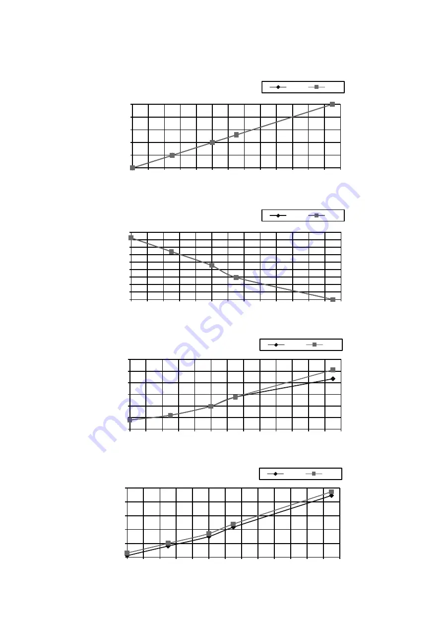
Panasonic CS-PC12TKF Service Manual Download Page 74

74 

17.2.2 CS-PC18TKF 

CU-PC18TKF 

 Cooling 

Characteristic 

[Condition] Room 

temperature: 27°C (DBT), 19°C (WBT) 


Operation condition: High fan speed 


Piping length: 5.0 m 


14.500

15.000

15.500

16.000

16.500

17.000

30

32

34

36

38

40

42

44

46

48

50

52

54

56

In

doo

D

is

ch

ar

ge

Air

T

e

m

p

e

ra

tu

re

Outdoor Temperature (℃)

220V

240V

4.000

4.200

4.400

4.600

4.800

5.000

5.200

5.400

5.600

5.800

30

32

34

36

38

40

42

44

46

48

50

52

54

56

Ca

pa

ci

ty

(kW

Outdoor Temperature (℃)

220V

240V

9.000

10.000

11.000

12.000

13.000

14.000

30

32

34

36

38

40

42

44

46

48

50

52

54

56

Cu

rr

ent

A

Outdoor Temperature (℃)

220V

240V

0.450

0.500

0.550

0.600

0.650

0.700

0.750

30

32

34

36

38

40

42

44

46

48

50

52

54

56

Ga

s

S

id

e

Pipin

g

Pre

ssu

re

(M

Pa

)

Outdoor Temperature (℃)

220V

240V


Summary of Contents for CS-PC12TKF

Page 1: ...s powered by electricity should be serviced or repaired only by experienced professional technicians Any attempt to service or repair the products dealt with in this service information by anyone else could result in serious injury or death There are special components used in this equipment which are important for safety These parts are marked by in the Schematic Diagrams Circuit Board Diagrams E...

Page 2: ...eration 44 12 4 Indoor Fan Speed Control 45 12 5 Outdoor Fan Speed Control 47 12 6 Vertical Airflow Direction Control 47 12 7 Horizontal Airflow Direction Control 50 12 8 JETSTREAM Operation 51 12 9 Quiet Operation 53 12 10 Timer Control 54 12 11 Sleep Mode Operation 54 12 12 Random Auto Restart Control 54 12 13 Remote Control Signal Receiving Sound 54 13 Protection Control 55 13 1 Restart Control...

Page 3: ... Keep plastic bag packaging material away from small children it may cling to nose and mouth and prevent breathing 8 When installing or relocating air conditioner do not let any substance other than the specified refrigerant eg air etc mix into refrigeration cycle piping Mixing of air etc will cause abnormal high pressure in refrigeration cycle and result in explosion injury etc 9 Do not add or re...

Page 4: ...and accumulates at surrounding of the unit it may cause fire 2 Do not release refrigerant during piping work for installation re installation and during repairing a refrigeration parts Take care of the liquid refrigerant it may cause frostbite 3 Do not install this appliance in a laundry room or other location where water may drip from the ceiling etc 4 Do not touch the sharp aluminium fin sharp p...

Page 5: ... 5k Indoor Fan Type Cross Flow Fan Cross Flow Fan Material ASG20K1 ASG33 Motor Type DC Motor 8 poles DC Motor 8 poles Input Power W 51 0 58 0 94 8 94 8 Output Power W 24 40 Speed QLo rpm 740 880 Lo rpm 810 970 Me rpm 980 1040 Hi rpm 1150 1120 SHi rpm 1180 1200 Outdoor Fan Type Propeller Fan Propeller Fan Material PP Resin PP Resin Motor Type AC Induction 6 poles AC Induction 4 poles Input Power W ...

Page 6: ...in Type Slit Fin Slit Fin Row Stage FPI 2 15 17 2 17 17 Size W H L mm 610 315 25 4 836 357 25 4 Outdoor Heat Exchanger Fin Material Aluminium Blue coated Aluminium Blue coated Fin Type Corrugate Fin Slit Fin Row Stage FPI 1 20 17 1 28 17 Size W H L mm 22 508 0 708 4 12 7 588 0 865 3 Air Filter Material Polypropelene Polypropelene Type One touch One touch Power Supply Indoor Indoor Power Supply Cor...

Page 7: ...Fan Type Cross Flow Fan Material ASG33 Motor Type DC Motor 8 poles Input Power W 94 8 94 8 Output Power W 40 Speed QLo rpm 910 Lo rpm 1000 Me rpm 1100 Hi rpm 1220 SHi rpm 1300 Outdoor Fan Type Propeller Fan Material PP Resin Motor Type AC Induction 6 poles Input Power W 157 3 173 8 Output Power W 88 Speed Lo rpm 440 500 Hi rpm 860 890 Moisture Removal L h Pt h 4 0 8 5 Indoor Airflow QLo m 3 min ft...

Page 8: ... Slit Fin Row Stage FPI 2 17 17 Size W H L mm 836 357 25 4 Outdoor Heat Exchanger Fin Material Aluminium Blue coated Fin Type Slit Fin Row Stage FPI 2 31 17 Size W H L mm 25 4 651 866 6 846 6 Air Filter Material Polypropelene Type One touch Power Supply Indoor Power Supply Cord A 20 Thermostat Protection Device Mechanical DRY BULB WET BULB Indoor Operation Range Maximum C F 32 89 6 23 73 4 Minimum...

Page 9: ...wer failure for safety restart operation o Gas leakage protection o Prevent compressor reverse cycle o Overload protector to protect compressor o Noise prevention during soft dry operation o Blue coated condenser for high resistance to corrosion Operation Improvement o Quiet mode to reduce the indoor unit operating sound o Jetstream mode to reach the desired room temperature quickly o 24 hour time...

Page 10: ...distances 8m Horizontal airflow direction louver Manually adjustable Front Panel Aluminium Fin 4 1 2 CS PC18TKF CS PC24TKF Front Panel Horizontal airflow direction louver Manually adjustable INDICATOR Green Orange Auto OFF ON button Use when remote control is misplaced or a malfunction occurs Aluminium Fin Vertical Airflow Direction Louver Do not adjust by hand Remote Control Receiver Maximum dist...

Page 11: ... Remote Control Remote control display JETSTREAM operation Operation mode OFF ON Quiet operation Fan Speed selection Airflow direction selection Temperature setting Timer setting Sleep operation Clock setting ...

Page 12: ...ection Air outlet direction Left piping hole Side View Right piping hole 560 6 420 16 4 264 6 380 496 6 128 184 15 35 128 222 Left piping hole Installation plate Relative position between the indoor and the installation plate Front View Indoor unit external dimensions line Right piping hole Unit mm 92 8 60 60 55 41 61 410 Gas side Liquid side Rear View 60 41 64 87 Remote Control Holder Remote Cont...

Page 13: ...xternal dimensions line Installation plate Unit mm 16 5 264 550 550 128 210 260 Top View Front View Bottom View Rear View Side View Side View Remote Control Holder Remote Control 41 61 Air inlet direction 244 Liquid side Gas side Left piping hole 43 61 302 42 6 61 Air outlet direction Right piping hole 135 60 135 60 410 59 144 5 22 1102 128 128 256 256 64 87 ...

Page 14: ...w Side View Front View Top View Unit mm 2 way valve at Liquid side High Pressure 3 way valve at Gas side Low Pressure 5 2 2 CU PC18TKF 3 way valve at Gas side Low Pressure 2 way valve at Liquid side High Pressure 124 540 160 37 37 299 32 167 330 619 183 62 69 20 357 824 63 22 Anchor Bolt Pitch 330 x 540 Space necessary for installation Side View 10cm 10cm 100cm Side View Top View Front View Unit m...

Page 15: ...45 7 7 613 34 7 131 875 35 82 360 5 131 72 Space necessary for installation Anchor Bolt Pitch 360 5 613 100 cm 10 cm 10 cm Side View Side View Front View Top View Unit mm 2 way valve at Liquid side High Pressure 3 way valve at Gas side Low Pressure ...

Page 16: ...ycle Diagram COMPRESSOR 3 WAY VALVE GAS SIDE LIQUID SIDE CAPILLARY TUBE HEAT EXCHANGER CONDENSER 2 WAY VALVE PIPE TEMP SENSOR INTAKE AIR TEMP SENSOR HEAT EXCHANGER EVAPORATOR INDOOR OUTDOOR STRAINER THERMOSTAT PC24TK only ...

Page 17: ...17 7 Block Diagram 7 1 CS PC12TKF CU PC12TKF INDOOR UNIT OUTDOOR UNIT INDOOR POWER SUPPLY SC C FM VA301 U FUSE301 RY PWR FM 2 1 L N COMP M 1 FAN MOTOR TEMP FUSE 102 C 250V 4 5A ...

Page 18: ...18 7 2 CS PC18TKF CU PC18TKF INDOOR UNIT OUTDOOR UNIT SC VA301 U FUSE301 RY PWR FM 2 1 L N COMP TEMP FUSE 102 C 250V 3A M INDOOR POWER SUPPLY FAN MOTOR ...

Page 19: ...19 7 3 CS PC24TKF CU PC24TKF SC VA301 U FUSE301 RY PWR TEMP FUSE 102 C 250V 3A M FAN MOTOR INDOOR UNIT OUTDOOR UNIT C FM C COMP FM 2 L N COMP THERMOSTAT 1 ...

Page 20: ... MOTOR CIRCUIT ELECTRONIC CONTROLLER DISPLAY RECEIVER T3 15A L250V BR ELECTRONIC CONTROLLER MAIN SINGLE PHASE POWER SUPPLY TEMP FUSE 102 C 250V 4 5A P L 1 M M 1 M 1 YELLOW YELLOW OR GRAY BLUE BLUE RED BLUE RED BLUE FAN MOTOR CAPACITOR COMPRESSOR CAPACITOR TERMINAL BOARD 1 2 REMARKS BL BLACK B BLU BLUE BR BROWN G GRN GREEN O ORANGE P PINK R RED W WHT WHITE Y G YELLOW GREEN Y YLW YELLOW Resistance o...

Page 21: ... B Y BL W WW W W W 1 8 1 1 9 4 4 7 1 5 4 CN STM1 WHT CN STM3 BLU CN TH RED CN DISP YLW CN RCV YLW CN FM WHT FAN MOTOR EVAPORATOR SINGLE PHASE POWER SUPPLY GROUNDING TERMINAL ELECTRONIC CONTROLLER MAIN GROUNDING TERMINAL TERMINAL BOARD NOISE FILTER CIRCUIT RECTIFICATION CIRCUIT ELECTRONIC CONTROLLER DISPLAY RECEIVER CN DISP WHT REMOTE CONTROLLER FUSE301 RY PWR T3 15A L250V AC303 WHT G301 GRN G W BL...

Page 22: ... G W B Y BL W WW W W W 1 8 1 1 9 4 4 7 1 5 4 CN STM1 WHT CN STM3 BLU CN TH RED CN DISP YLW CN RCV YLW CN FM WHT FAN MOTOR EVAPORATOR SINGLE PHASE POWER SUPPLY GROUNDING TERMINAL ELECTRONIC CONTROLLER MAIN GROUNDING TERMINAL TERMINAL BOARD NOISE FILTER CIRCUIT RECTIFICATION CIRCUIT ELECTRONIC CONTROLLER DISPLAY RECEIVER CN DISP WHT REMOTE CONTROLLER FUSE301 RY PWR T3 15A L250V AC303 WHT G301 GRN G ...

Page 23: ... 250V 4 5A P L 1 M M 1 M 1 YELLOW YELLOW OR GRAY BLUE BLUE RED BLUE RED BLUE FAN MOTOR CAPACITOR COMPRESSOR CAPACITOR TERMINAL BOARD 1 2 Sensor Thermistor Characteristics 70 60 50 40 30 20 10 0 10 0 10 Temperature ºC Resistance kΩ 20 30 40 50 1 2 1 2 Pipe temp Sensor Intake Air Temp Sensor 5V R58 NONE KB C29 0 033u 50V R36 1k 12V IC02 1 2 3 4 5 6 7 16 15 14 13 12 11 10 8 GND VCC 9 12V R04 1 2W 43 ...

Page 24: ...ICATION CIRCUIT ELECTRONIC CONTROLLER DISPLAY RECEIVER CN DISP WHT REMOTE CONTROLLER FUSE301 RY PWR T3 15A L250V AC303 WHT G301 GRN G W BL Y G L P BR L N 1 2 TEMP FUSE 102 C 250V 3A M Sensor Thermistor Characteristics 70 60 50 40 30 20 10 0 10 0 10 Temperature ºC Resistance kΩ 20 30 40 50 1 2 1 2 Pipe temp Sensor Intake Air Temp Sensor 5V R201 R202 R203 LED201 A K LED202 A K LED203 A K LED204 A K ...

Page 25: ...RCUIT RECTIFICATION CIRCUIT ELECTRONIC CONTROLLER DISPLAY RECEIVER CN DISP WHT REMOTE CONTROLLER FUSE301 RY PWR T3 15A L250V AC303 WHT G301 GRN G W BL Y G L P BR L N 1 2 TEMP FUSE 102 C 250V 3A M Sensor Thermistor Characteristics 70 60 50 40 30 20 10 0 10 0 10 Temperature ºC Resistance kΩ 20 30 40 50 1 2 1 2 Pipe temp Sensor Intake Air Temp Sensor 5V R201 R202 R203 LED201 A K LED202 A K LED203 A K...

Page 26: ...26 10 Printed Circuit Board 10 1 Indoor Unit 10 1 1 Main Printed Circuit Board 10 1 1 1 CS PC12TKF CN FB RY PWR AC303 CN PCFM CN STM1 CN STM3 SW01 CN TH CN DISP JX02 Random Auto Restart Enable Disable ...

Page 27: ...27 10 1 1 2 CS PC18TKF CS PC24TKF AC303 RY PWR G301 CN FM SW01 CN STM1 CN STM3 CN TH CN DISP CN RCV JX02 Random Auto Restart Enable Disable ...

Page 28: ...28 10 1 2 Indicator and Receiver Printed Circuit Board 10 1 2 1 CS PC12TKF CN DISP 10 1 2 2 CS PC18TKF CS PC24TKF CN DISP ...

Page 29: ...12 1 5HP 12 7 mm 1 2 6 35 mm 1 4 5 5 3 15 10 7 5 PC18 2 0HP 20 3 30 20 7 5 PC24 2 5HP 15 88 mm 5 8 20 3 30 30 7 5 Example For PC12 If the unit is installed at 10 m distance the quantity of additional refrigerant should be 25 g 10 7 5 m x 10 g m 25 g 11 1 3 Indoor Outdoor Unit Installation Diagram 50 mm or more 65 mm or more Left and right are identical Installation plate 1 Sleeve Bushing Sleeve Be...

Page 30: ...0 mm 15 mm 35 mm 3 4 5 6 Ceiling Wall Wall Installation plate 1 2 screw More than 1 More than 1 Measuring Tape Indoor unit More than 2 For best strength of INDOOR unit installation it is highly recommended to locate at 5 position as shown 256 mm 128 mm 128 mm 256 mm 128 mm Model Dimension 1 2 3 4 5 6 PC18 PC24 605 mm 95 mm 550 mm 550 mm 210 mm 260 mm The center of installation plate should be at m...

Page 31: ...he meeting point of the extension arrow mark is the hole center position o Drill the piping hole at either the right or the left and the hole should be slightly slanting to the outdoor side refer to step 11 2 2 11 2 2 To Drill a Hole in the Wall and Install a Sleeve of Piping 1 Insert the piping sleeve to the hole 2 Fix the bushing to the sleeve 3 Cut the sleeve until it extrudes about 15 mm from ...

Page 32: ...e outdoor piping and gas leakage confirmation Connect the piping Please refer to Insulation of piping connection column as mentioned in indoor outdoor unit installation Install the Indoor Unit Secure the Indoor Unit Insulate and finish the piping Step 1 Step 2 Step 3 Step 4 Step 5 Step 6 Step 7 Step 8 In case of the cover is cut keep the cover at the rear of chassis as shown in the illustration fo...

Page 33: ...ing holder that mounted on the wall 2 Open the front panel and grille door by loosening the screw 3 Cable connection to the power supply through Isolating Devices Disconnecting means o Connect the approved polychloroprene sheathed power supply cord 3 x 1 5 mm2 1 5HP or 3 x 2 5 mm2 2 0 2 5HP type designation 60245 IEC 57 or heavier cord to the terminal board and connect the other end of the cable t...

Page 34: ... by tighten with screw and close the front panel Terminal Board Control Board Earth wire longer than others AC wires for safety reason Holder Holder Connection cable Indoor outdoor connection cable Isolating Devices Outdoor unit Power supply cord Power supply cord Recommended length mm Tape Recommended length mm a b c d e f 55 35 35 50 40 60 Tape WARNING This equipment must be properly earthed Not...

Page 35: ...tor not fully inserted 5 mm or more Indoor outdoor connection terminal board gap between wires ACCEPT PROHIBITED PROHIBITED WARNING RISK OF FIRE JOINING OF WIRES MAY CAUSE OVERHEATING AND FIRE Do not joint wires OR OR OR Use complete wire without joining Use approved socket and plug with earth pin Wire connection in this area must follow to national wiring rules ...

Page 36: ...f tube assembly onto the copper pipe In case of using long piping Connect the piping Align the center of piping and sufficiently tighten the flare nut with fingers Further tighten the flare nut with torque wrench in specified torque as stated in the table Do not over tighten overtightening may cause gas leakage Piping size Torque 6 35 mm 1 4 18 N m 1 8 kgf m 9 52 mm 3 8 42 N m 4 3 kgf m 12 7 mm 1 ...

Page 37: ...ng set and turn off the vacuum pump Make sure that the needle in the gauge does not move after approximately five minutes Note BE SURE TO TAKE THIS PROCEDURE IN ORDER TO AVOID REFRIGERANT GAS LEAKAGE 5 Disconnect the charging hose from the vacuum pump and from the service port of the 3 way valve 6 Tighten the service port caps of the 3 way valve at a torque of 18 N m with a torque wrench 7 Remove ...

Page 38: ...ee for one minute Repeat this three times 7 Set the both 2 way and 3 way valves to open position with the Hexagonal wrench for the unit operation Control board cover Gas side Liquid side 2 way valve open Cap 3 way valve open Hexagonal wrench Service port cap Terminal board Over 5 mm 5 To open 2 way valve again turn the valve stem counter clockwise until it stop To indoor unit Liquid side Indoor un...

Page 39: ...ase the insulation by using POLY E FOAM with thickness 6 mm or above 11 3 6 1 Cutting and Flaring the Piping 1 Please cut using pipe cutter and then remove the burrs 2 Remove the burrs by using reamer If burrs is not removed gas leakage may be caused Turn the piping end down to avoid the metal powder entering the pipe 3 Please make flare after inserting the flare nut onto the copper pipes 1 To cut...

Page 40: ...mpressor ON Intake air temperature Remote control setting temperature 1 5 C higher than setting temperature 12 1 1 Cooling Operation Time Diagram For PC12TKF Intake Air Temperature 1 5 C Description of operation d g s u a b g h q u h o Minimum 60 seconds forced operation Minimum 3 minutes restart control Time Delay Safety Control Maximum 7 minutes time save control Freeze Prevention control Operat...

Page 41: ... Set Temp Outdoor Temp 31 C 29 C 1 5K Intake Temp 10 C Pipe Temp 2 C Description of operation d g a b g h o p q t v y h o restart control waiting for 3 min 60 sec Forcible operation freeze prevention control outdoor fan control 7 min time save control Operation Stop Compressor Basic time Indoor Fan Outdoor Fan Operation LED 1 3 4 7 1 1 ...

Page 42: ...Cooling mode if the intake temperature is higher than Cooling ON point Compressor ON Cooling ON point 1 5ºC Cooling OFF Soft Dry ON point Soft Dry OFF point 1 0ºC Soft Dry ON point Cooling Dry Dry OFF Intake air temperature Compressor OFF 12 2 1 Soft Dry Operation Time Diagram For PC12TKF Intake Temp ON Dry OFF ON Basic Time 1 1 1 4 Compressor Indoor Fan Outdoor Fan Operation LED OFF Set Temp Cool...

Page 43: ... Temperature 1 5ºC 1 0ºC Time Frame Compressor Indoor Fan Auto Fan Speed Outdoor Fan Operation LED Description of operation h i l m o p v w Minimum 60 seconds forced operation n o Minimum 3 minutes restart control Time Delay Safety Control Cooling operation f h i k s u Minimum 6 minutes restart control Time Delay Safety Control Soft dry operation q v Freeze Prevention Control Operation Stop a b c ...

Page 44: ...le below Setting Temperature Standard Cooling Operation 25 C Soft Dry Operation 22 C The setting temperature for all the operations can be changed one level up or one level down from the standard temperature as shown in below table by pressing on the temperature up or temperature down button at remote control Cooling Soft Dry Higher 2 C 27 C 24 C Standard 0 C 25 C 22 C Lower 2 C 23 C 20 C The oper...

Page 45: ...an speed is adjusted between maximum and minimum setting as shown in the table o Fan speed rotates in the range of Hi and Me o Deodorizing Control will be activated For PC12TKF Speed Mode SHi Hi Me HLo CLo Lo SLo Stop Cooling Normal Manual Hi Me Lo Auto Quiet Manual QHi Hi 70 QMe Me 70 QLo CLo 70 Auto Hi 70 Me 70 Jetstream Soft Dry Normal Manual Auto Quiet Manual Auto Mode Judgment For PC18 24TKF ...

Page 46: ...or 1 2 Stop ON ON OFF Lo Lo Variable RPM Stop Lo Lo 1 Fan Speed is Hi until the compressor stops when the room temperature reaches setting temperature Fan Speed is Me after the compressor restarts 2 Auto Fan Speed during Soft Dry operation 1 Indoor fan will rotate alternately between off and Lo 2 At the beginning of each compressor starts operation indoor fan will increase fan speed gradually for ...

Page 47: ... Auto using the remote control the louver swings up and down as shown in the diagram When stops operation using the remote control the discharge vent is reset and stops at the closing position During Cooling operation or Soft Dry operation indoor fan motor may stop to rotate at certain periods At that condition the louver will stop swinging For PC12TKF Inner Vane Stopper Closed Position Reference ...

Page 48: ...Upper Limit for Cooling Mode 140 Cooling Dry Mode Airflow direction auto or manual Lower Limit 90 0 148 90 140 Outer Vane 101 Stopper Closed Position Reference Point 0 47 74 Cooling Dry Mode Airflow direction auto or manual Lower Limit 74 Upper Limit for Cooling Mode 47 ...

Page 49: ...d louver position When stop operation using the remote control the discharge vent is reset and stop at the closing position For PC12TKF Inner Vane Stopper Closed Position Reference Point Upper Limit for Cooling Mode 10 Cooling Dry Mode Airflow direction auto or manual Lower Limit 45 0 110 01 45 30 20 15 10 Outer Vane Stopper Closed Position Reference Point Upper Limit for Cooling Mode 20 Cooling D...

Page 50: ...auto or manual Lower Limit 90 0 148 90 105 120 135 140 Outer Vane 101 Stopper Closed Position Reference Point 0 47 58 64 69 74 Cooling Dry Mode Airflow direction auto or manual Lower Limit 74 Upper Limit for Cooling Mode 47 12 7 Horizontal Airflow Direction Control The horizontal airflow direction louvers can be adjusted manually by hand ...

Page 51: ... Operation Mode Cool Manual 10 down from previous step setting Auto Auto air swing with range shift 10 down Control condition o JETSTREAM operation start condition When JETSTREAM button at remote control is pressed When unit in OFF operation and JETSTREAM button at remote control is pressed Unit will turn ON under COOL mode and JETSTREAM operation o JETSTREAM operation stop condition When one of t...

Page 52: ... changed only the display alone is changed as JET STREAM FAN When Jet Stream is cancelled turn OFF fan speed displays actual Cool mode fan speed When Jet Stream is cancelled turn OFF fan speed displays actual Cool mode fan speed Note Air swing settings are not changed under Jet Stream Just follow current setting Refer to Jet Stream cancel methods below ...

Page 53: ...Lo 30 minutes QLo 50 rpm Manual Airflow Direction o RPM control during Lo cool Quiet LED Fan OFF OFF CLo ON QLo 1 hr 30 min 1 hr 30 min QLo QLo 50 QLo 50 QLo 100 QLo 100 o RPM control during Hi Me cool Quiet LED Fan OFF OFF Hi Me Q Hi Q Me Q Hi Q Me Hi Me Press Quiet Press Quiet Cancel Quiet ON ON Time Hour Auto Fan Speed Indoor fan Compressor ON ON OFF Quiet Hi if before thermo off Quiet ME after...

Page 54: ...rn temperature during the activation period The indoor unit indicator will dim when this operation is activated This is not applicable if the indicator brightness has been manually dimmed This operation is incorporated with the activation timer 0 5 1 2 3 4 5 6 7 8 or 9 hours This operation can be set together with timer Sleep operation has the priority over OFF timer This operation can be cancelle...

Page 55: ...er is turned on the compressor will not stop within 60 seconds in a normal operation although the intake air temperature has reached the thermo off temperature However force stop by pressing the OFF ON button at the remote control is permitted The reason for the compressor to force operation for minimum 60 seconds is to allow the refrigerant oil run in a full cycle and return back to the outdoor u...

Page 56: ... times within 50 minutes unit will turns OFF with TIMER indicator blinks The 5 Times counter can be reset when either one of the following condition happen o Unit is OFF by remote control or AUTO OFF ON button o Indoor intake temperature Indoor piping temperature 5 C for 1 minute or more o Operation mode change The unit could be ON by pressing OFF ON button at remote control but the TIMER LED will...

Page 57: ...Auto OFF ON button to toggle remote control receiving sound Short beep Turn ON remote control receiving sound Long beep Turn OFF remote control receiving sound After Auto OFF ON button is pressed the 20 seconds counter for Remote Control Receiving Sound OFF ON Mode is restarted ii Remote Control Number Switch There are 4 types of remote control transmission code could be selected and stored in EEP...

Page 58: ...irm low limit selection o Press TEMP increment or decrement button to choose No 4 o Press Timer decrement or increment button to select desired temperature high limit of set temperature for COOL DRY mode o Press Timer Set button to confirm high limit selection o LCD returns to original display if remote control does not operate for 30 seconds or press Timer Cancel button 14 2 2 RESET To clear and ...

Page 59: ...If any 2 Cannot enter this special setting mode under the following conditions 1 Operation ON 2 Under Real ON OFF time setting mode 3 To enter zone 1 area Enter Zone1 range 1 49 Normal display mode 4 To enter zone 2 area Press continuously for T 5 secs Once T 5secs Enter Zone2 range 50 99 Enter Zone1 Normal display mode ...

Page 60: ...le disable selection 00 01 10 Auto restart enable disable selection 00 01 11 Dust sensor sensitivity level adjustment 1 2 3 12 49 Reserve Zone 2 50 ECO demo ON None No display 51 Light sensor check None No display 52 nanoe G ECO sensor check None No display 53 DOA check None No display 54 Odor cut control selection Enable 01 Disable 00 00 01 55 Frequency tolerance selection 3Hz 03 7Hz 07 03 07 56 ...

Page 61: ...r Temperature Standard Gas Pressure MPa kg cm 2 G Outlet air Temperature C Cooling Mode 0 4 0 6 4 6 12 16 Condition Indoor fan speed High Outdoor temperature 35 C Different in the intake and outlet air temperatures Normal Value of electric current during operation Dusty condenser preventing heat radiation Excessive amount of refrigerant Gas side pressure Inefficient compressor Insufficient refrige...

Page 62: ...lectric current and temperature fifteen minutes after an operation is started 15 1 2 Diagnosis Methods of a Malfunction of a Compressor Nature of fault Symptom Insufficient compressing of a compressor Electric current during operation becomes approximately 20 lower than the normal value The discharge tube of the compressor becomes abnormally hot normally 70 C to 90 C The different between high pre...

Page 63: ...n electric shocks 16 1 CS PC12TKF 16 1 1 Indoor Electronic Controllers and Control Board Removal Procedures 16 1 1 1 To Remove Front Grille 3 Hold both sides of the front grille and remove it by pulling up and toward yourself gently 1 Lift to open the horizontal vane gently 2 Remove 2 caps and 3 screws at the bottom of discharge vane Figure 1 16 1 1 2 To Remove Electronic Controller 4 Removing the...

Page 64: ...M CN STM1 CN STM3 CN TH 8 Pull out the main electronic controller halfway 5 Detach the Earth wire screw 7 Remove screw to remove terminal board complete 6 Detach the CN DISP connector then remove the indicator complete Figure 3 Figure 4 16 1 1 3 To Remove Discharge Grille 11 Pull out to remove the drain hose from the discharge grille 12 Then pull the discharge grille downward gently to dismantle i...

Page 65: ...then pull out the control board Figure 6 16 1 1 5 To Remove Cross Flow Fan and Indoor Fan Motor 13 Remove the screw that holding the cross flow fan and fan motor axis Figure 7 Holdfast 16 Remove the bearing by pulling it out gently 15 Remove the 2 screw from the evaporator Figure 8 ...

Page 66: ...t and downward Evaporator 18 Fan motor can be removed after the removal of cross flow fan Reminder To reinstall the fan motor please adjust the connector to 45 with fan motor before fixing control board Figure 9 Reminder To reinstall the cross flow fan ensure cross flow fan is in line as shown in figure 10 Cross Flow Fan Figure 10 ...

Page 67: ... Electronic Controllers Cross Flow Fan and Indoor Fan Motor Removal Procedures 16 2 1 1 To Remove Front Grille 3 Hold both sides of the front grille and remove it by pulling up and toward yourself gently 1 Lift to open the horizontal vane gently 2 Remove 3 caps and 4 screws at the bottom of discharge vane and 1 screw at the front grille Figure 1 16 2 1 2 To Remove Horizontal Vane 4 Removing the co...

Page 68: ...tach the indicator connector CN DISP then remove the indicator complete 7 Remove screw to remove terminal board complete and earth wire 5 Detach the Earth wire screw 8 Pull out the main electronic controller and power electronic controller halfway Figure 3 Figure 4 16 2 1 4 To Remove Discharge Grille 11 Pull out to remove the drain hose behind the discharge grille from the discharge grille outlet ...

Page 69: ... then pull out the control board Figure 6 16 2 1 6 To Remove Cross Flow Fan and Indoor Fan Motor 14 Remove the screw that holding the cross flow fan and fan motor axis Figure 7 16 Remove the screw from the evaporator Holdfast 15 Remove the bearing by pulling it out gently Figure 8 ...

Page 70: ... to the left and downward 19 Fan motor can be removed after the removal of cross flow fan Reminder To reinstall the fan motor please adjust the connector to 45 with fan motor before fixing control board Figure 9 Reminder To reinstall the cross flow fan ensure cross flow fan is in line as shown in figure 10 Cross Flow Fan Figure 10 ...

Page 71: ...ºC ºC 30 30 28 28 26 26 24 24 22 22 20 20 18 18 16 16 COMP OFF Set Temperature Intake Air Temperature Diff 1 5k Soft Dry Thermostat Setting Remote Control Cooling ON Cooling OFF ºC ºC 30 30 28 28 26 26 24 24 22 22 20 20 18 18 16 16 Dry OFF Dry ON Set Temperature Intake Air Temperature Diff 1 5k Diff 1 0k ...

Page 72: ...56 Indoor Discharge Air Temperature Outdoor Temperature 220V 240V 2 600 2 800 3 000 3 200 3 400 3 600 3 800 30 32 34 36 38 40 42 44 46 48 50 52 54 56 Capacity kW Outdoor Temperature 220V 240V 5 000 5 500 6 000 6 500 7 000 7 500 8 000 30 32 34 36 38 40 42 44 46 48 50 52 54 56 Current A Outdoor Temperature 220V 240V 0 528 0 530 0 532 0 534 0 536 0 538 0 540 0 542 0 544 0 546 30 32 34 36 38 40 42 44 ...

Page 73: ... 4 5 6 7 8 9 10 11 12 13 14 15 Indoor Discharge Air Temperature Piping Length m 220V 240V 3 300 3 400 3 500 3 600 3 700 3 4 5 6 7 8 9 10 11 12 13 14 15 Capacity kW Piping Length m 220V 240V 5 300 5 400 5 500 5 600 5 700 5 800 5 900 3 4 5 6 7 8 9 10 11 12 13 14 15 Current A Piping Length m 220V 240V 0 527 0 528 0 529 0 530 0 531 0 532 3 4 5 6 7 8 9 10 11 12 13 14 15 Gas Side Piping Pressure MPa Pip...

Page 74: ... Air Temperature Outdoor Temperature 220V 240V 4 000 4 200 4 400 4 600 4 800 5 000 5 200 5 400 5 600 5 800 30 32 34 36 38 40 42 44 46 48 50 52 54 56 Capacity kW Outdoor Temperature 220V 240V 9 000 10 000 11 000 12 000 13 000 14 000 30 32 34 36 38 40 42 44 46 48 50 52 54 56 Current A Outdoor Temperature 220V 240V 0 450 0 500 0 550 0 600 0 650 0 700 0 750 30 32 34 36 38 40 42 44 46 48 50 52 54 56 Ga...

Page 75: ...31 Indoor Discharge Air Temperature Piping Length m 220V 240V 4 400 4 600 4 800 5 000 5 200 5 400 3 5 7 9 11 13 15 17 19 21 23 25 27 29 31 Capacity kW Piping Length m 220V 240V 8 800 9 000 9 200 9 400 9 600 9 800 10 000 10 200 3 5 7 9 11 13 15 17 19 21 23 25 27 29 31 Current A Piping Length m 220V 240V 0 430 0 440 0 450 0 460 0 470 0 480 0 490 0 500 0 510 0 520 3 5 7 9 11 13 15 17 19 21 23 25 27 2...

Page 76: ... Temperature Outdoor Temperature 220V 240V 5 000 5 500 6 000 6 500 7 000 7 500 8 000 30 32 34 36 38 40 42 44 46 48 50 52 54 56 Capacity kW Outdoor Temperature 220V 240V 11 000 12 000 13 000 14 000 15 000 16 000 17 000 18 000 30 32 34 36 38 40 42 44 46 48 50 52 54 56 Current A Outdoor Temperature 220V 240V 0 420 0 440 0 460 0 480 0 500 0 520 0 540 0 560 0 580 30 32 34 36 38 40 42 44 46 48 50 52 54 ...

Page 77: ...29 31 Indoor Discharge Air Temperature Piping Length m 220V 240V 5 900 6 100 6 300 6 500 6 700 6 900 7 100 3 5 7 9 11 13 15 17 19 21 23 25 27 29 31 Capacity kW Piping Length m 220V 240V 11 000 11 200 11 400 11 600 11 800 12 000 12 200 12 400 12 600 3 5 7 9 11 13 15 17 19 21 23 25 27 29 31 Current A Piping Length m 220V 240V 0 360 0 380 0 400 0 420 0 440 0 460 3 5 7 9 11 13 15 17 19 21 23 25 27 29 ...

Page 78: ...6 7 2 3 37 38 39 5 4 31 17 14 21 19 20 8 16 15 36 28 12 20 35 25 34 30 18 32 33 29 26 11 10 22 CWH55025J CWH55051J I I O I I I 27 32 24 24A 23 23A Note The above exploded view is for the purpose of parts disassembly and replacement The non numbered parts are not kept as standard service parts ...

Page 79: ...M 1 ACXH62 00120 22 CAP DRAIN TRAY 1 CWH521259 23 AIR SWING MOTOR 1 CWA981264 O 23A AIR SWING MOTOR 1 CWA981299 O 24 HORIZONTAL VANE COMPLETE BIG 1 ACXE24C01090 24A HORIZONTAL VANE COMPLETE SMALL 1 ACXE24C00950 25 CONTROL BOARD TOP COVER 1 ACXH13 00700 26 CONTROL BOARD FRONT COVER CO 1 ACXH13C00180 27 REMOTE CONTROL COMPLETE 1 ACXA75C04210 O 28 FRONT GRILLE COMPLETE 1 ACXE10C03050 O 29 INTAKE GRIL...

Page 80: ...9 40 41 36 33 7 8 6 4 3 2 1 16 18 19 30 31 11 10 15 38 28 25 21 24 22 9 13 32 23 23 14 I I O I I I 29 17 34 35 34 27 27A 26 26A Note The above exploded view is for the purpose of parts disassembly and replacement The non numbered parts are not kept as standard service parts ...

Page 81: ...CHASSIS 1 CWD933463B CWD933067B 21 FULCRUM 2 ACXH62 00080 22 VERTICAL VANE 8 ACXE24 00400 23 VERTICAL VANE 3 ACXE24 00630 24 CONNECTING BAR LEFT 1 ACXE26 00190 25 CONNECTING BAR RIGHT 1 ACXE26 00200 26 HORIZONTAL VANE COMPLETE BIG 1 ACXE24C01030 26A HORIZONTAL VANE COMPLETE SMALL 1 ACXE24C00540 27 AIR SWING MOTOR 1 CWA981304 O 27A AIR SWING MOTOR 1 CWA981299 O 28 CAP DRAIN TRAY 1 CWH521259 29 REMO...

Page 82: ...KF 10 15 17 16 34 33 27 28 36 37 38 20 21 14 13 11 23 31 4 1 9 7 5 3 6 8 22 30 32 12 40 39 Note The above exploded view is for the purpose of parts disassembly and replacement The non numbered parts are not kept as standard service parts ...

Page 83: ...LIQUID 1 CWB021362 O 17 3 WAY VALVE GAS 1 CWB011482 O 20 TERMINAL COVER 1 CWH171012 21 NUT TERMINAL COVER 1 CWH7080300J 22 SOUND PROOF BOARD 1 CWH151430 23 SOUND PROOF MATERIAL 1 CWG302673 27 TERMINAL BOARD ASSY 1 CWA28K1272 O 28 CABINET SIDE PLATE CO 1 ACXE04C00770 30 CABINET SIDE PLATE 1 CWE041858A 31 CABINET FRONT PLATE ASSY 1 CWE06K1116 32 CABINET TOP PLATE 1 CWE031230A 33 PLATE C B COVER 1 CW...

Page 84: ...7 33 18 17 8 30 10 9 14 1 15 16 3 25 24 20 2 7 6 4 29 11 5 23 19 35 34 13 12 21 22 23 Note The above exploded view is for the purpose of parts disassembly and replacement The non numbered parts are not kept as standard service parts ...

Page 85: ...E GAS 1 CWB011105 O 17 TERMINAL COVER 1 CWH171012 18 NUT TERMINAL COVER 1 CWH7080300J 19 PACKING 3 CWB81043 20 SOUND PROOF BOARD 1 ACXH15 00350 21 CAPACITOR FM 1 DS441456CPNC O 22 CAPACITOR COMP 1 DS441355NPQA O 23 HOLDER CAPACITOR 1 CWH30060 24 SOUND PROOF MATERIAL 1 ACXG30 04840 25 SOUND PROOF MATERIAL 1 ACXG30 04850 26 TERMINAL BOARD ASSY 1 CWA28K1064J O 27 CABINET SIDE PLATE CO 1 ACXE04C03180 ...

Page 86: ...8 23 38 26 30 33 34 12 16 10 11 1 17 18 27 28 14 15 22 21 13 39 29 7 4 35 24 31 32 40 Note The above exploded view is for the purpose of parts disassembly and replacement The non numbered parts are not kept as standard service parts ...

Page 87: ...E LIQUID 1 CWB021574 O 18 3 WAY VALVE GAS 1 CWB011484 O 21 TERMINAL COVER 1 CWH171012 22 NUT TERMINAL COVER 1 CWH7080300J 23 SOUND PROOF BOARD 1 ACXH15 00310 24 TERMINAL BOARD ASS Y 1 CWA28K1272 O 26 CAPACITOR COM 1 CWA312079 O 27 HOLDER CAPACITOR 1 CWH30060 28 CAPACITOR F M 1 DS441505NPQB O 29 CABINET SIDE PLATE 1 ACXE04 00490A 30 CABINET SIDE PLATE COMPLETE 1 ACXE04C03190 31 CABINET FRONT PLATE ...

Reviews: