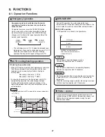
This function prevents the circuit breaker or fuse from operating
to open the circuit. This function works when electrical current
has increased due to an increase in the cooling / heating load,
or to a decrease in the power supply voltage. In these cases,
operation frequency is reduced or operation is interrupted auto-
matically to control the electrical current for operation.
When the cause of the increase in electrical current is rectified,
the system will resume operation in the original mode.
•
•
Electrical current setting for COOL operation is
used during DEFROST operation.
Cooling Dry
Heating
Peak current cut-off trips
22.5
Hz down
14.0
15.0
(A)
<CS-KE12NB41>
CT (Peak current cut-off control)
NOTE
Cooling Dry
Heating
Peak current cut-off trips
17.5
Hz down
11.0
14.0
(A)
<CS-KE18NB4UW>
NOTE
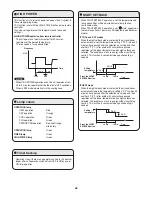
Heating operation
Frost sensing
Reverse-cycle defrosting operation
Defrosting Sequence
Releasing of defrosting
Outdoor fan ON
4-way valve ON
Outdoor heating exchanger temp. is over 68
°
F(20
°
C).
Defrosting operation lasts 12 minutes (maximum).
2 minutes after it is stopped, compressor is ON.
4-way valve is ON. Outdoor fan is ON.
If the air conditioner is turned off during the defrosting
cycle, it will continue defrosting and turn itself off after
defrosting is completed.
Compressor 1 minute after it is stopped,
compressor is ON.
Outdoor fan OFF
Indoor fan OFF
4-way valve OFF
Operation lamp
Reverse-Cycle Defrosting
Defrost detection and release
Repeatedly switches between red
and orange illumination.
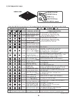
Defrost detection occurs in either of the following cases:
The temperature of the heat exchanger remains at
or below the L2 line for 120 minutes after the start
of HEAT operation.
Outdoor heat
exchanger temp.
Ambient temp.
0
L1
L2
Frosting area
The temperature of the heat exchanger remains at
or below the L1 line for 3 minutes after the start of
HEAT operation.
•
•
50
Summary of Contents for CS-KE12NB41
Page 36: ...8FA2 5251 12200 2 Outdoor Unit CU KE12NK1 36 ...
Page 69: ......
Page 89: ......
Page 114: ...Operating Instructions CZ RD515U 852 6 4181 230 00 1 APPENDIX C A 3 ...
Page 125: ......
Page 126: ...A 4 INSTALLATION INSTRUCTIONS CZ RD515U 852 6 4190 592 00 0 APPENDIX D ...
Page 131: ......
Page 132: ...DC1111 0 ...

