17
5-4. Connecting Tubing between Indoor and
Outdoor Units
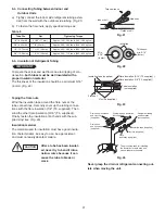
a)
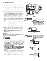
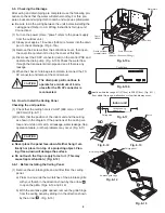
Tightly connect the indoor side refrigerant tubing exten-
ded from the wall with the outdoor side tubing. (Fig. 21)
b)
To fasten the flare nuts, apply specified torque as:
Table 5
5-5. Insulation of Refrigerant Tubing
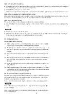
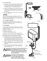
To prevent heat loss and wet floors due to dripping of con-
densation,
both tubes must be well insulated with a
proper insulation material.
The thickness of the insulation should be a minimum 5/16"
(8 mm). (Fig. 22)
IMPORTANT
Fig. 21
Fig. 22
Insulation
Min.
5/16"
(8 mm)
Thickness:
min. 5/16"
(8 mm)
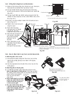
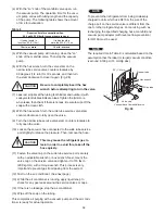
Taping the flare nuts
Wind the insulation tape around the flare nuts at the
tube connections. Secondly cover up the tubing connec-
tions with the flare insulation (1/8" (T3, supplied)). Then
wind the other flare insulation (3/16" (T5, supplied)).
Finally, fasten the insulation at both ends with the sup-
plied vinyl ties. (Fig. 23)
Insulation material
The material used for insulation must have good insula-
tion characteristics, be easy to use, be age resistant,
and must not easily absorb moisture.
After a tube has been insulat-
ed, never try to bend it into a
narrow curve because it can
cause the tube to break or
crack.
CAUTION
Fig. 23
Fig. 24
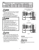
Never grasp the drain or refrigerant connecting out-
lets when moving the unit.
Indoor unit
Outdoor unit
Spanner
Torque wrench
Insulation tape (supplied)
Flare insulation (3/16"(T5, supplied) )
Flare insulation (1/8"(T3, supplied) )
Tube insulation
(not supplied)
Vinyl tie (supplied)
Flare nut
The procedure used for installing
the insulation for both wide and
narrow tubes are the same.
Flare
insulation (supplied)
Vinyl tie (supplied)
Insulation tape (supplied)
Refrigerant tubing
and insulation
(not supplied)
Drain pipe and insulation
(not supplied)
Drain hose insulation
and vinyl tie
(supplied)
Drain hose
and hose band
(supplied)
Tube Dia.
Nut
Tightening Torque
1/4" (6.35 mm)
21/32" (17 mm)
Approx. 120 – 160 lbs·in (140 – 180 kgf·cm)
3/8" (9.52 mm)
7/8" (22 mm)
Approx. 300 – 360 lbs·in (340 – 420 kgf·cm)
1/2" (12.70 mm)
1-1/32" (26 mm)
Approx. 430 – 480 lbs·in (490 – 550 kgf·cm)
5/8" (15.88 mm)
1-5/32" (29 mm)
Approx. 590 – 710 lbs·in (680 – 820 kgf·cm)
Summary of Contents for CS-KE12NB41
Page 36: ...8FA2 5251 12200 2 Outdoor Unit CU KE12NK1 36 ...
Page 69: ......
Page 89: ......
Page 114: ...Operating Instructions CZ RD515U 852 6 4181 230 00 1 APPENDIX C A 3 ...
Page 125: ......
Page 126: ...A 4 INSTALLATION INSTRUCTIONS CZ RD515U 852 6 4190 592 00 0 APPENDIX D ...
Page 131: ......
Page 132: ...DC1111 0 ...

