


95
WARNING
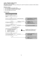
16. Disassembly and Assembly Instructions
High Voltage is generated in the electrical parts area by the capacitor. Ensure that the capacitor has discharged sufficiently before proceeding with
repair work. Failure to heed this caution may result in electric shocks.
16.1 Disassembly of Parts
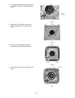
1 Open the Intake Grille from the Front Grille by
moving the catchers to center (Fig.1).
Fig. 1
2 Remove the Control Board Cover by removing
the screws (Fig. 2).
Fig. 2
3 Release the (Fig. 3):
o
CN-STM1 (WHT) connector.
o
CN-STM2
(YLW)
connector.
o
CN-DISP
(WHT)
connector.
o
CN-FM (WHT) connector.
o
CN-TH1 (WHT) connector.
o
CN-TH2
(BLU)
connector.
o
CN-DRMTR1
(BLU)
connector.
o
AC01 (BLK), AC02 (WHT) and
CN-DRMTR2 (RED) from Terminal
Board.
o
G01
(GRN)
screw.
o
Two T-BLK connectors.
o
CN-T1
(WHT).
o
CN-T2
(
YLW).
Fig. 3
Summary of Contents for CS-E9PB4EA
Page 24: ...24 4 Location of Controls and Components 4 1 Indoor Unit 4 2 Outdoor Unit 4 3 Remote Control...
Page 25: ...25 5 Dimensions 5 1 Indoor Unit...
Page 26: ...26 5 2 Outdoor Unit 5 2 1 CU E9PB4EA 5 2 2 CU E12PB4EA...
Page 27: ...27 6 Refrigeration Cycle Diagram 6 1 CS E9PB4EA CU E9PB4EA...
Page 28: ...28 6 2 CS E12PB4EA CU E12PB4EA...
Page 29: ...29 7 Block Diagram 7 1 CS E9PB4EA CU E9PB4EA...
Page 30: ...30 7 2 CS E12PB4EA CU E12PB4EA...
Page 31: ...31 8 Wiring Connection Diagram 8 1 Indoor Unit...
Page 34: ...34 9 Electronic Circuit Diagram 9 1 Indoor Unit...
Page 35: ...35 9 2 Outdoor Unit 9 2 1 CU E9PB4EA...
Page 36: ...36 9 2 2 CU E12PB4EA...
Page 37: ...37 10 Printed Circuit Board 10 1 Indoor Unit 10 1 1 Main Printed Circuit Board...
Page 38: ...38 10 1 2 Display Printed Circuit Board...
Page 39: ...39 10 2 Outdoor Unit 10 2 1 CU E9PB4EA...
Page 40: ...40 10 2 2 CU E12PB4EA...
Page 65: ...65 14 3 2 CU E12PB4EA...
Page 106: ...106 18 Exploded View and Replacement Parts List 18 1 Indoor Unit...


