


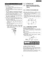


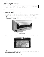


CUTTING AND FLARING THE PIPING
1. Please cut using pipe cutter and then remove the burrs.
2. Remove the burrs by using reamer. If burrs is not
removed, gas leakage may be caused.
Turn the piping end down to avoid the metal powder
entering the pipe.
3. Please make flare after inserting the flare nut onto the
copper pipes.
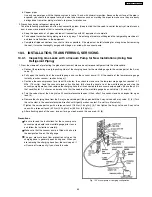
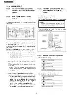
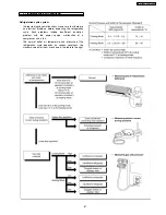
11.3.4. (a) EVACUATION OF THE EQUIPMENT (FOR EUROPE & OCEANIA DESTINATION)
WHEN INSTALLING AN AIR CONDITIONER, BE SURE TO EVACUATE THE AIR INSIDE THE INDOOR UNIT AND PIPES in the
following procedure.
1. Connect a charging hose with a push pin to the Low and High side of a charging set and the service port of the 3-way valve.
•
Be sure to connect the end of the charging hose with the push pin to the service port.
2. Connect the center hose of the charging set to a vacuum pump with check valve, or vacuum pump and vacuum pump adaptor.
3. Turn on the power switch of the vacuum pump and make sure that the needle in the gauge moves from 0 cmHg (0 MPa) to
-76 cmHg (-0.1 MPa). Then evacuate the air approximately ten minutes.
4. Close the Low side valve of the charging set and turn off the vacuum pump. Make sure that the needle in the gauge does not
move after approximately five minutes.
Note: BE SURE TO FOLLOW THIS PROCEDURE IN ORDER TO AVOID REFRIGERANT GAS LEAKAGE.
5. Disconnect the charging hose from the vacuum pump and from the service port of the 3-way valve.
6. Tighten the service port caps of the 3-way valve at torque of 18 N.m with a torque wrench.
7. Remove the valve caps of both of the 2-way valve and 3-way valve. Position both of the valves to “OPEN” using a hexagonal
wrench (4 mm).
8. Mount valve caps onto the 2-way valve and the 3-way valve.
•
Be sure to check for gas leakage.
CAUTION
•
If gauge needle does not move from 0 cmHg (0 MPa) to -76 cmHg (-0.1 MPa), in step 3 above take the following measure:
•
If the leak stops when the piping connections are tightened further, continue working from step 3.
•
If the leak does not stop when the connections are retightened, repair the location of leak.
•
Do not release refrigerant during piping work for installation and reinstallation. Take care of the liquid refrigerant, it may cause
frostbite.
64
CS-E15CKP CU-E15CKP5
Summary of Contents for CS-E15CKP
Page 8: ...4 Dimensions 8 CS E15CKP CU E15CKP5 ...
Page 9: ...9 CS E15CKP CU E15CKP5 ...
Page 10: ...5 Refrigeration Cycle Diagram 10 CS E15CKP CU E15CKP5 ...
Page 11: ...6 Block Diagram 11 CS E15CKP CU E15CKP5 ...
Page 12: ...7 Wiring Diagram 12 CS E15CKP CU E15CKP5 ...
Page 39: ...IONIZE 42 43 44 41 39 CS E15CKP CU E15CKP5 ...
Page 40: ...IONIZER IONIZER IONIZER IONIZER 40 CS E15CKP CU E15CKP5 ...
Page 41: ...CZ SFD72P 41 CS E15CKP CU E15CKP5 ...
Page 42: ...42 CS E15CKP CU E15CKP5 ...
Page 43: ... H23 H27 H28 43 CS E15CKP CU E15CKP5 ...
Page 44: ...44 CS E15CKP CU E15CKP5 ...
Page 45: ...45 CS E15CKP CU E15CKP5 ...
Page 75: ...13 Technical Data 75 CS E15CKP CU E15CKP5 ...
Page 87: ...87 CS E15CKP CU E15CKP5 ...
Page 88: ...How to use electronic circuit diagram 88 CS E15CKP CU E15CKP5 ...
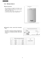
Page 89: ...18 1 REMOTE CONTROL 89 CS E15CKP CU E15CKP5 ...
Page 90: ...18 2 PRINT PATTERN INDOOR UNIT PRINTED CIRCUIT BOARD 90 CS E15CKP CU E15CKP5 ...
Page 91: ...18 3 PRINT PATTERN OUTDOOR UNIT PRINTED CIRCUIT BOARD VIEW 91 CS E15CKP CU E15CKP5 ...
Page 92: ...92 CS E15CKP CU E15CKP5 ...
Page 93: ...93 CS E15CKP CU E15CKP5 MAICO Printed in Malaysia ...
Page 94: ......


