
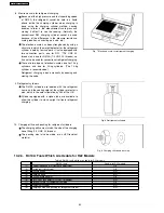


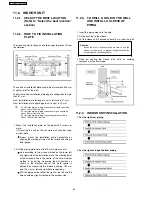


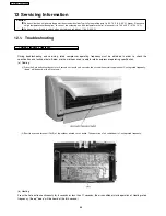
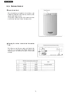


AUTO SWITCH OPERATION
The below operations will be performed by pressing the
“AUTO” switch.
1. AUTO OPERATION MODE
The Auto operation will be activated immediately once the
Auto Switch is pressed.
2. TEST RUN OPERATION (FOR PUMP DOWN/SERVICING
PURPOSE)
The Test Run operation will be activated if the Auto Switch
is pressed continuously for more than 5 sec. to below 10
sec.. A “pep” sound will occur at the fifth sec., in order to
identify the starting of Test Run operation
3. HEATING CONTROLLER RECEIVING SOUND ON/OFF
The ON/OFF of remote controller receiving sound can be
changed over by following steps:
4. REMOTE CONTROLLER RECEIVING SOUND ON/OFF
The ON/OFF of remote controller receiving sound can be
changed over by following steps:
a. Press “AUTO” switch continuously for more than 16 sec.
to below 21 sec. A “pep” “pep” sound will occur at
sixteenth sec..
b. Press the “Check” button once at remote controller. A
“pep” sound will occur.
c.
Press the “AUTO” switch once to select remote
controller receiving sound ON/OFF. A “pep” sound
indicates receiving sound ON, and a “pep” sound
indicates receiving sound OFF.
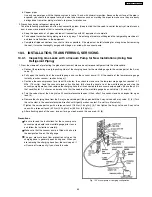
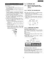
11.3. OUTDOOR UNIT
11.3.1. SELECT THE BEST LOCATION
(Refer to “Select the best location”
section)
11.3.2. INSTALL THE OUTDOOR UNIT
•
After selecting the best location, start installation according
to Indoor/Outdoor Unit Installation Diagram.
1. Fix the unit on concrete or rigid frame firmly and horizontally
by bolt nut. (ø10 mm).
2. When installing at roof, please consider strong wind and
earthquake. Please fasten the installation stand firmly with
bolt or nails.
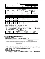
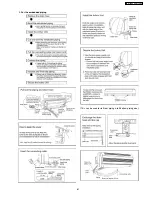
11.3.3. CONNECTING THE PIPING
Connecting The Piping To Indoor Unit
Please make flare after inserting flare nut (locate at joint portion
of tube assembly) onto the copper pipe. (In case of using long
piping)
Connect the piping
•
Align the center of piping and sufficiently tighten the flare
nut with fingers.
•
Further tighten the flare nut with torque wrench in specified
torque as stated in the table.
MODEL
Piping size (Torque)
Gas
Liquid
E9CK
3/8” (42 N.m)
1/4” (18 N.m)
E12CK, E15CK
1/2” (55 N.m)
1/4” (18 N.m)
Connecting The Piping To Outdoor Unit
Decide piping length and then cut by using pipe cutter. Remove
burrs from cut edge. Make flare after inserting the flare nut
(located at valve) onto the copper pipe.
Align center of piping to valves and then tighten with torque
wrench to the specified torque as stated in the table.
63
CS-E15CKP CU-E15CKP5
Summary of Contents for CS-E15CKP
Page 8: ...4 Dimensions 8 CS E15CKP CU E15CKP5 ...
Page 9: ...9 CS E15CKP CU E15CKP5 ...
Page 10: ...5 Refrigeration Cycle Diagram 10 CS E15CKP CU E15CKP5 ...
Page 11: ...6 Block Diagram 11 CS E15CKP CU E15CKP5 ...
Page 12: ...7 Wiring Diagram 12 CS E15CKP CU E15CKP5 ...
Page 39: ...IONIZE 42 43 44 41 39 CS E15CKP CU E15CKP5 ...
Page 40: ...IONIZER IONIZER IONIZER IONIZER 40 CS E15CKP CU E15CKP5 ...
Page 41: ...CZ SFD72P 41 CS E15CKP CU E15CKP5 ...
Page 42: ...42 CS E15CKP CU E15CKP5 ...
Page 43: ... H23 H27 H28 43 CS E15CKP CU E15CKP5 ...
Page 44: ...44 CS E15CKP CU E15CKP5 ...
Page 45: ...45 CS E15CKP CU E15CKP5 ...
Page 75: ...13 Technical Data 75 CS E15CKP CU E15CKP5 ...
Page 87: ...87 CS E15CKP CU E15CKP5 ...
Page 88: ...How to use electronic circuit diagram 88 CS E15CKP CU E15CKP5 ...
Page 89: ...18 1 REMOTE CONTROL 89 CS E15CKP CU E15CKP5 ...
Page 90: ...18 2 PRINT PATTERN INDOOR UNIT PRINTED CIRCUIT BOARD 90 CS E15CKP CU E15CKP5 ...
Page 91: ...18 3 PRINT PATTERN OUTDOOR UNIT PRINTED CIRCUIT BOARD VIEW 91 CS E15CKP CU E15CKP5 ...
Page 92: ...92 CS E15CKP CU E15CKP5 ...
Page 93: ...93 CS E15CKP CU E15CKP5 MAICO Printed in Malaysia ...
Page 94: ......


