


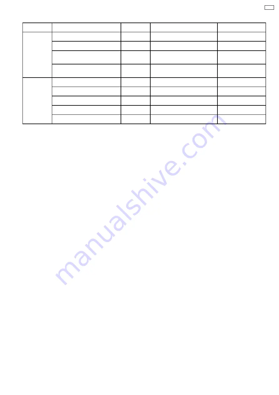
Switching
Position
Initial Motor Direction
Switching
Mode
Initial Motor Direction
Function
Home
Position
Cam gear rotate CCW to HOME
Motor :
CCW
C
UD base move from bottom to top
Motor :
CW
Tray selection from bottom
to top
Cam gear rotate CCW to HOME
Motor :
CCW
D
UD base move from top to bottom
Motor :
CCW
Tray selection from top to
bottom
UD base move from bottom to top
Motor :
CW
E
Cam gear rotate CW from HOME to
Play Driving Position. Motor :
CW
After tray selection, cam
gear rotate to Play Driving
Position
UD base move from top to bottom
Motor :
CCW
G
Cam gear rotate CW from HOME to
Play Driving Position. Motor :
CW
After tray selection, cam
gear rotate to Play Driving
Position
Play
Driving
Position
Cam gear rotate CW from HOME to Play
Driving Position. Motor :
CW
A
Drive tray from STOCK position to
PLAY position. Motor :
CW
Load tray to Play
Cam gear rotate CW from HOME to Play
Driving Position. Motor :
CW
B
Drive tray from PLAY position to
STOCK position. Motor :
CCW
Unload tray from Play to
Stock
Drive tray from STOCK position to PLAY
position. Motor :
CW
F
Cam gear rotate CCW from Play
Driving Position to HOME. Motor :
CCW
After load tray to Play, cam
gear return to HOME
Drive tray from PLAY position to STOCK
position. Motor :
CCW
H
Cam gear rotate CCW from Play
Driving Position to HOME. Motor :
CCW
After unload tray from Play,
cam gear return to HOME
Drive tray from PLAY position to STOCK
position. Motor :
CCW
G
Cam gear rotate CW from until trays full
open. Motor :
CW
Open trays while one tray
Play
·
Switching mode G is used during initialization to ensure that the switching gear is at the release (down) condition before the
initialization process begins.
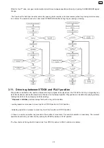
3.7. Initialization of Mechanism Unit.
·
Mechanism Initialization
-- This mechanism is designed to operate & set to a pre-defined position to prevent malfunction when
unavoidable circumstances happen. For examples: user mis-handling during transportaion or abnormal user operations.This is
comply to the product shipping reliability standards.
·
Mechanism is initialized when the mechanism controller is unable to detect the present condition/state of mechanism. For
example, when the microcomputer carries out a cold start. (In complete unit)
·
Once the initialization process is completed, the mechanism unit is set to this condition:-
1. Tray 1 is at PLAY position (Top tray)
2. The traverse unit is at clamping condition (PLAY SW-L)
3. All the remaining trays are in STOCK Position (Trays 2 ~ 5 )
4. Plunger lever at release condition
5. Cam gear is at Home position ( HOME SW-L)
6. Motor is free (CW-L, CCW-L)
Note: This is same as shipment condition. (In complete unit)
·
Below is the flow chart of the initialization process:-
15
CRS1
Summary of Contents for CRS1
Page 3: ...1 Mechanism Overview 3 CRS1 ...
Page 28: ... For tray 1 selection flow chart below will be used 28 CRS1 ...
Page 48: ...48 CRS1 ...
Page 52: ...CRS1 52 ...
Page 97: ...12 Exploded Views 12 1 CD Loading Mechanism 97 CRS1 ...
Page 98: ...98 CRS1 ...
Page 99: ...99 CRS1 ...


