3
Description of Parts
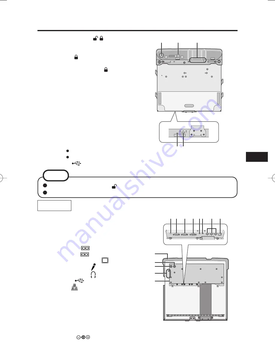
A
B
C
D E
A. Key insertion slot
B. Lever
DOCK UNDOCK
Slide the lever to the direction of “DOCK”, then turn
the key toward side to lock. When the computer
has been installed, be absolutely sure to lock this
lever by turning the key toward side.
C. Expansion Bus Connector
D. Dock indicator
DOCKED
GREEN : all ports are ready to use
ORANGE
:
USB port and LAN port do
not function, due to no
external power is connected
RED : Connected PC is not supported
or connection error happens
RED (Blinking):
An error has occured in the
fi
rmware.
Stop using at once, and contact
Panasonic Technical Support.
Not lit: PC has not installed.
PC is OFF, Standby or Hibernation.
E. USB port
NOTE
The lock was turned to side in the default setting.
When installing the computer, con
fi
rm that the lever is slid toward the UNDOCK side.
A B C D EF G H
I
J
K
L
M
Bottom
A. Wireless Antenna Switch
Switch the antenna of the PC or the
antenna connected with this Car Mounter.
Turn toward EXT side when use the
antenna connected with this Car Mounter.
B. Serial Port B
C. Serial Port A
D. External display port
E. Microphone jack
F. Headphone jack
G. USB ports
H. LAN port
I. Security
lock
LOCK
You can connect a Kensington cable. Refer
to the instruction manual of the cable.
J. External ANT A LOWER Port of
computer/single
(optional)
K. External ANT B UPPER Port of computer
(optional)
L. (optional)
M. DC-IN jack
DC IN 15.6V
%(9'$&(39<#6KPFF
%(9'$&(39<#6KPFF


