background image

70

BL-C111A /BL-C131A

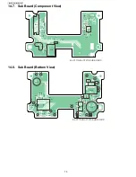
14.7. Sub Board (Component View)

14.8. Sub Board (Bottom View)

C821

C818

C816

C817

C802

R853

R852

R851

SA851

C851

C870

C871

C884

+

C872

C873

R860

R859

R801

L801

20

CN801

1

2

SW802

L853

C869

C868

C867

C852

R857

R858

R856

1

3

1

IC852

PQUP11471Z

A

PbF

BL-C111A/BL-C131A SUB BOARD

TP_LED_G

Lens

C806

C808

C814

LED801

IC804

AMP

C803

R803

R809

R819

R811

Q801

TP_LED_R

R818

R808

D801

IC851

C863

C858

C861

MICAMP1

MICAMP2

30

1

C865

R855

C860

MIC851

C859

C856

DA3.3V

A3.3VA

C854 C857

C855

L851

AGND1

AGND2

IC802

2

3

1

C807

C819

C801

SW801

L852

GND2

GND1

C813

Q802

C809

C804

C805

R805

R807

R810

R804

R802

R806

TP_SEN

C853

C862

C866

C864

16

15

R854

MIC

MICG

12

IC801

BL-C111A/BL-C131A SUB BOARD

Summary of Contents for BL C131A - Network Camera - Pan

Page 1: ... 2007 Panasonic Communications Co Ltd All rights reserved Unauthorized copying and distribu tion is a violation of law ORDER NO KMS0701303CE F15 Network Camera BL C111A BL C131A for U S A ...

Page 2: ...37 8 15 How To Change MAC Address Label 38 8 16 How to Replace a Flat Package IC 39 9 Disassembly and Assembly Instructions 40 9 1 Disassembly Instructions BL C111A 40 9 2 Disassembly Instructions BL C131A 44 10 Maintenance 49 10 1 Cleaning 49 11 Factory Setting 50 11 1 Resetting the Camera 50 11 2 Resetting the Camera Using the FACTORY DEFAULT RESET Button 50 12 Block Diagram 51 13 Schematic Diag...

Page 3: ...USHITA 1 2 About Lead Free Solder PbF Pb free Note In the information below Pb the symbol for lead in the periodic table of elements will refer to standard solder or solder that con tains lead We will use PbF solder when discussing the lead free solder used in our manufacturing process which is made from Tin Sn Silver Ag and Copper Cu This model and others like it manufactured using lead free sold...

Page 4: ... use Tin and Copper Sn Cu or Tin Zinc and Bismuth Sn Zn Bi Please check the manufac turer s specific instructions for the melting points of their products and any precautions for using their product with other materi als The following lead free PbF solder wire gauge are recommended for service of this product 0 3mm 0 6mm and 1 0mm 1 2 2 How to Recognize That Pb Free Solder is Used MAIN BOARD ...

Page 5: ...5 BL C111A BL C131A LENS BOARD I O BOARD ...

Page 6: ... trademarks or trademarks of Adobe Systems Incorporated in the United States and or other countries Ethernet is a registered trademark of Xerox Corporation in the United States and or other countries Microsoft Windows and Active X are either registered trademarks or trademarks of Microsoft Corporation in the United States and or other countries Pentium is a registered trademark of Intel Corporatio...

Page 7: ...NS ICMPv6 POP3 NDP NTP RTP RTSP RTCP Image Buffer Transfer Triggers Timer Sensor Motion Detection Image Transfer Method SMTP 4 FTP HTTP Wired LAN Interface 10Base T 100Base TX Ethernet RJ 45 connector Sensor Detection Method Pyroelectric Infrared Sensor Sensor Detection Range 5 Horizontal About 30 Vertical About 85 Distance About 5 m 16 feet 5 inches when in a 20 C 68 F environment Indicator Displ...

Page 8: ...F 2 1 Internal Memory Capacity for Buffered Images The camera s internal memory can buffer images according to the table below Note All values are approximate JPEG images videos and still images MPEG 4 videos For information about MPEG 4 image capacity see the Panasonic Network Camera website at http panasonic co jp pcc products en netwkcam Resolution Specification Snapshot Image Quality Favor Cla...

Page 9: ...d or when the camera detects motion You can program the camera to buffer these camera images and then you can play back these images later while accessing the camera or save them to your PC You can also program the camera to transfer images by E mail or upload them to an FTP or HTTP server as they are being buffered Digital zoom When viewing camera images from a PC you can zoom up to 10X by area a...

Page 10: ...dependent Interface I F FLASH MEMORY IC102 Operating Power Supply 3 3V Package 48 pin Ball DGA Capacity 64Mbit Access Time 60ns Outline of Operation Stores programs for CPU operation MAC address and customer setup data Version up is available from Ethernet I F SDRAM IC103 IC104 Operating Power Supply 3 3V Package 54 pin TSOP Capacity 64Mbit Outline of Operation Stores the memory for CPU work and t...

Page 11: ...ge is converted into digital using the 10 bit AD Converter ADC At that time Correlated Double Sampling CDS dramatically decreases Formulaic Pattern Noise FPN Analogue pixel voltage data which is converted to digital is finished using Gammacorrection Color Correction and Color Space Conversion Those signals are sent out as digital format 8bit span Y UV with PCLK Hsync and Vsync signals as a timing ...

Page 12: ...12 BL C111A BL C131A 4 1 4 Power Supply Block Power Supply Block provides power that each block consumes Input is DC 9V 750mA from AC adaptor The circuit diagram and output voltage are showed as below ...

Page 13: ...s temperature variation into analogue signal which it emits when a heat source such as a person comes into detection area The analogue signal is amplified by Operational Amplifier IC802 2 Circuits Built in Operational Amplifier IC802 Operating Power Supply 3 3V Package 8 pin SSOP Amplifies analogue signal from Pyroelectric Infrared Sensor IC801 Operation of Pyroelectric Infrared Sensor 1 Pyroelect...

Page 14: ... Control Block A Tilt motor operates when CPU IC101 on a main board controls the motor driver IC IC402 on the same board A Constant Voltage Bipolar Drive System is employed The Voltage of Motor Power VM is 3 3V ø15 Stepping Motors are employed 4 1 9 LED Control Block LED is controlled by CPU which is mounted on Main Board Control data is input into LED Control Circuit which is mounted on Sub Board...

Page 15: ...fied by the amplifier in the PCM Codec IC851 and the ALC IC852 then input as the built in microphone to the PCM Codec IC851 again When the level of the input sound signal is more than the specified value the gain is changed and the output signal level is kept constant at the ALC IC852 Sound distortion is controlled when the input is excessive 2 In the PCM Codec IC851 after the sound signal is swit...

Page 16: ...and Quadrature RxQ to output The baseband signal is input to the CPU MAC BB RFIC IC601 and after A D conversion the data are regenerated Transmitter The Data Frame Data Packet generated at the built in MAC Part by the CPU MAC BB RFIC IC601 is converted to the RF Signal of the transmitting frequency band After processing including impedance conversion level adjustment and control of the unnecessary...

Page 17: ...17 BL C111A BL C131A 5 Location of Controls and Components ...

Page 18: ...18 BL C111A BL C131A 6 Installation Instructions ...

Page 19: ...19 BL C111A BL C131A ...

Page 20: ...works already use it When your ISP supports IPv6 your Panasonic Network Camera will be ready For more information visit http www ipv6 org Note Refer to the Panasonic Network Camera website at http panasonic co jp pcc products en netwkcam for details about net work environment Item Requirement Operating System For IPv4 Connection Microsoft Windows VistaTM 1 Windows XP Windows 2000 For IPv6 Connecti...

Page 21: ...21 BL C111A BL C131A 7 2 Connection ...

Page 22: ...e a backup of all camera settings on your PC or restore all settings in the camera using a backup file saved on your PC Network Camera Recorder Single Camera Version Installation Installs the Network Camera Recorder Single Camera Version software See Installing the Network Camera Recorder Single Camera Version on page 2 Exit Closes the screen and exits the Setup Program If you have more than one c...

Page 23: ...he WIRELESS WIRED switch on the bottom of the camera to WIRELESS 3 Plug the AC adaptor in to the power outlet Confirm that the indicator lights green after about 1 minute If the indicator does not light green see 1 2 Camera Indicator Issues in the Troubleshooting Guide on the CD ROM 4 Start your web browser and access the camera Enter camera s IP address that was displayed during setup then press ...

Page 24: ...24 BL C111A BL C131A 8 Troubleshooting Guide 8 1 Starting Up Operation 1 It does not turn on when LED mode is OFF on web setup menu ...

Page 25: ...25 BL C111A BL C131A 1 It does not turn on when LED mode is OFF on web setup menu ...

Page 26: ...26 BL C111A BL C131A 8 2 Indicator view Check ...

Page 27: ...27 BL C111A BL C131A 8 3 LAN Block Check 8 3 1 Green Light On ...

Page 28: ...28 BL C111A BL C131A 8 3 2 Orange Light Blinking 1 ...

Page 29: ...29 BL C111A BL C131A 8 3 3 Orange Light Blinking 2 ...

Page 30: ...30 BL C111A BL C131A 8 4 Camera Block Check ...

Page 31: ...31 BL C111A BL C131A 8 5 Power Supply Block Check ...

Page 32: ...32 BL C111A BL C131A 8 6 Other Operation Check 8 6 1 PAN Operation Check 8 6 2 TILT Operation Check ...

Page 33: ...33 BL C111A BL C131A 8 7 Pyroelectric Infrared Sensor Check ...

Page 34: ...34 BL C111A BL C131A 8 8 Sound Block Check ...

Page 35: ...35 BL C111A BL C131A 8 9 RF Block Check BL C131A ...

Page 36: ...ck PAN TILT operation Pyroelectric Infrared Sensor Video quality 8 11 Diagnosis NG Check When turning on the power CPU makes a check using the self diagnosis function Check being able to the access to the device described below When the self diagnosis function of the device described below is NG turning on the power CPU makes a check using the LED indicator red blinks ...

Page 37: ...ot turn the power off during execution of work 3 Renew the MAC Address label 8 13 In Case Where the RF Board Is Replaced C131A only Rewrite the MAC Address of the RF board 1 Turn on the power after replacing the RF board after a old MAC has been written to the main board Confirm that the WIRELESS WIRED switch on the bottom of the camera is set to WIRELESS 2 Press the Factory Default Reset button a...

Page 38: ...bel included with the main board Attach the new MAC address label to the unit by placing over the old MAC address label Make sure the old address cannot be seen Throw away the old main board It cannot be reused If the MACaddress of the old main board is already registered via DDNS and thenused in a different camera the camera can not be used with DDNS service ...

Page 39: ...e P 3 8 16 2 Procedure 1 Tack the flat pack IC to the PCB by temporarily soldering two diagonally opposite pins in the correct positions on the PCB Be certain each pin is located over the correct pad on the PCB 2 Apply flux to all of the pins on the IC 3 Being careful to not unsolder the tack points slide the sol dering iron along the tips of the pins while feeding enough solder to the tip so that...

Page 40: ...abel Make sure the old address cannot be seen Throw away the old main board It cannot be reused If the MACaddress of the old main board is already registered via DDNS and thenused in a different camera the camera can not be used with DDNS service 9 1 Disassembly Instructions BL C111A 9 1 1 How To Remove Main Board and I O Board 1 Remove two Screws A And remove the Cabinet Cover 2 Remove three Cabl...

Page 41: ...41 BL C111A BL C131A 5 Remove I O Board from Main Board 6 Remove Angle Screw D and Board Support Rubber from I O Board ...

Page 42: ... How To Remove Main Board and I O Board 5 Remove six Screws B 6 Remove Eye Block Pan Motor Unit Pan Motor Angle Connect Angle and Washer 7 Remove two Screws B 8 Remove Board support and Cabinet Cap from Cabinet Body 9 Remove two Screws B 10 Remove Sub Flat Cable from Sub Board ...

Page 43: ... 5 Remove three Screws B 6 Remove Eye Block and Pan Motor Unit 7 Remove two Screws B 8 Remove two Spacers Pan Gear and Pan Motor Unit from Eye Block 9 Delete solder of Main Flat Cable and remove Tilt Motor Unit 10 Remove two Screws B 11 Remove Eye Left Cover Eye Center Cover and Eye Right Cover from Lens Board ...

Page 44: ...tions BL C131A 9 2 1 How To Remove RF Board 1 Remove two Screws E And remove the Cabinet Cover 2 Remove Screw F and Antenna Cable 3 Remove Heat Rubber A and Heat Rubber B 4 Remove Antenna Cable from RF Board and remove RF Board from Cabinet body ...

Page 45: ... 2 2 How To Remove Main Board and I O Board 1 4 are the same as 9 2 1 How To Remove RF Board 5 Remove three Cable 6 Remove three Screws F 7 Remove Main Board and I O Board form Cabinet Body 8 Remove Main Board from I O Board ...

Page 46: ...RF Board 5 7 are the same as How To Remove Main Board and I O Board 9 Remove Angle Screw H and Board Support Rubber from I O Board 8 Remove two Screws F 9 Remove Antenna from Cabinet Body 10 Remove six Screws F 11 Remove Eye Block Pan Motor Unit Pan Motor Angle Connect Angle and Washer ...

Page 47: ... RF Board 5 7 are the same as 9 2 2 How To Remove Main Board and I O Board 8 9 are the same as 9 2 3 How To Remove Sub Board 12 Remove two Screws F and Board support 13 Remove two Screws F 14 Remove Sub Flat Cable from Sub Board 10 Remove three Screws F 11 Remove Eye Block and Pan Motor Unit ...

Page 48: ...Screws F 13 Remove two Spacers Pan Gear and Pan Motor Unit from Eye Block 14 Delete solder of Main Flat Cable and remove Tilt Motor Unit 15 Remove two Screws F 16 Remove Eye Left Cover Eye Center Cover and Eye Right Cover from Lens Board ...

Page 49: ...id pesticide glass cleaner or hair spray They may cause change in shape or color Do not apply pressure to the pan tilt portion of the camera Any forced movement can damage the internal mechanism If the pyroelectric infrared sensor has dust on it it may not detect temperature differences Keep the pyroelectric infrared sensor clean 10 1 2 Cleaning the Lens If the lens has dust on it the image may be...

Page 50: ...llowing information will be deleted All images buffered in the internal memory All alarm logs All camera settings including the user name password IP address subnet mask etc The network connection mode changes to Automatic Setup Reconfigure the camera by referring to the Setup Guide When the camera is reset the internal clock will not be reset but the time format will be set to AM PM mode Change t...

Page 51: ...5MHz RTC IC IC110 I2C BUS 32 768kHz CN401 28pin CN402 20pin CN108 AMP Filter Power LED LED801 20pin CN3 LENS SW SW801 20pin CN51 Battery BAT1 Motor Drive IC402 2 8V Regulator 20pin CN201 1 2V Regulator Sensor IC801 Clear Setting SW SW802 AC Adaptor 9V 64Mbit SDRAM 48MHz PCM CODEC IC851 ALC IC852 MIC TILT MOTOR 20pin CN661 Diversity Switch IC502 Power AMP IC501 16Mbit Flash IC602 64Mbit SDRAM IC603...

Page 52: ...Diagram 13 1 For The Schematic Diagram Note 1 DC voltage measurements are taken with an oscilloscope or a tester with a ground 2 The schematic diagrams and circuit board may be modified at any time with the development of new technology ...

Page 53: ...6 GPIO90 MII_COL J18 GPIO89 MII_CRS J17 GPIO88 MII_RXDV K15 GPIO87 MII_RXER K17 GPIO86 MII_RXD3 J14 GPIO85 MII_RXD2 K18 GPIO84 MII_RXD1 M19 GPIO83 MII_RXD0 J15 CLK216M U6 PLLBYPASS V3 PLLTESTIO V4 TEST1 P4 TEST0 N4 DBGCK G19 DBGD G18 MCK48O W6 MCK48I W7 RSTB U7 GPIO95 NMI J16 GPIO0 IRQ0 P18 GPIO1 IRQ1 T19 GPIO2 IRQ2 N16 GPIO3 IRQ3 P17 PLLVSS W4 PLLVDD W3 GPIO78 MII_TXD1 L18 GPIO77 MII_TXD0 N18 GPI...

Page 54: ...36 NC36 37 CKE 38 CLK 39 DQMH 40 NC40 41 VSS41 42 DQ8 43 VDDQ43 44 DQ9 45 DQ10 46 VSSQ46 47 DQ11 48 DQ12 49 VDDQ49 50 DQ13 51 DQ14 52 VSSQ52 53 DQ15 54 VSS54 C192 0 1u R145 47 C160 0 1u C204 0 1u 0 R249 R241 47 R125 47 C206 0 1u C201 0 1u R214 47 6 3V10u C209 DGND IC103 1 VDD1 2 DQ0 3 VDDQ3 4 DQ1 5 DQ2 6 VSSQ5 7 DQ3 8 DQ4 9 VDDQ9 10 DQ5 11 DQ6 12 VSSQ12 13 DQ7 14 VDD14 15 DQML 16 nWE 17 nCAS 18 nR...

Page 55: ...5 B1 A4 A1 A3 C1 A2 D1 A1 E1 A0 F1 nCE H1 VSS1 G1 nOE E2 DQ0 F2 DQ8 H2 DQ1 G2 DQ9 E3 DQ2 F3 DQ10 H3 DQ3 G3 DQ11 G4 VDD H4 DQ4 F4 DQ12 E4 DQ5 G5 DQ13 H5 DQ6 F5 DQ14 E5 DQ7 G6 DQ15 H6 VSS2 F6 NC E6 A16 R122 10K FROM_CS CPUAD 22 1 A3 PHYCP X201 25MHz L117 L113 NC 0 R150 NC R149 102 L111 C182 1u IC105 37 REXT 38 VDDRCV 39 GND39 40 TX 41 TX 42 NC42 43 NC43 44 GND44 45 XO 46 XI 47 VDDPLL 48 RST 13 VDDC ...

Page 56: ... Install RXN_IO TXN RXP_IO SW202 NC 1 2 3 4 5 6 RXP TXP_IO TXP TXN_IO RXN SW201 NC 1 2 3 4 5 6 TXN_IO TXN TXN_RF RXN_RF RXN RXN_IO RXP TXP_IO TXP_RF RXP_IO TXP RXP_RF CN201 NC 1 2 3 4 5 6 7 8 9 10 11 12 13 14 15 16 17 18 19 20 RF_NRST DGND DGND RF_LINK RXP_RF Q202 NC TXN_RF 0 1u C252 RXN_RF Q201 NC TXP_RF RXD2 DGND TXD2 9V RF_NPD 0 1u C251 R405 10K R406 10K 3 3V NC R143 NC R144 NC R148 NC R146 NC ...

Page 57: ... 2 3 4 R201 0 C410 NC CAMVDD CCDCLK DGND A_DTI R200 0 R202 0 A_DTO DGND PCM_CLK DGND RA402 220 1 2 3 4 5 6 7 8 DGND 3 3V 3 3V DGND PAN2 C402 0 1u A_FCK C417 6 3V10u TILT_PH2 TILT4 R154 47 C407 NC DGND C408 NC PCM_D DGND DGND DGND C421 100p PAN4 R404 3 3K DGND C412 NC LED_R CAM_NRST L410 L404 TILT_I11 TILT2 C419 NC DGND C422 15p C415 0 1u L406 TILT_PH1 TILT1 CN108 1 1 2 2 3 3 4 4 5 5 6 6 7 7 8 8 9 ...

Page 58: ...0 220p 6 3V10u C261 C259 0 1u CN51 1 2 3 4 5 6 7 8 9 10 11 12 13 14 15 16 17 18 19 20 9V IC107 1 NC 2 GND 3 CE 4 Vin 5 Vout TP_GND1 1 2V_VDDI TP_GND5 9V 3 3V TP_GND3 TP_GND4 TXN_IO TXP_IO PHYCP RXN_IO RXP_IO IICSCL IICSDA AC_STOP C4 1u Q1 E C B R13 2 7K C17 1u C16 0 1u D2 1 2 3 DGND R1 10K 3 3V R12 100 To IO Borad A4 ...

Page 59: ...3 R708 33 CN702 RE1 1 GND 2 PCLK 3 GND 4 SIO_C 5 SIO_D 6 VSYNC 7 HSYNC 8 GND 9 CLKIN 10 GND 11 RESET 12 PWDN 13 Y 7 14 Y 6 15 Y 5 16 Y 4 17 Y 3 18 Y 2 19 Y 1 20 Y 0 21 2 8V 22 2 8V 23 GND 24 GND CN701 1 VAA 2 CLKIN 3 TRSET 4 SCL 5 SDA 6 VDD 7 AGND 8 FV 9 LV 10 PCLK 11 DOUT0 12 DOUT1 13 DOUT2 14 DOUT3 15 PWRDN 16 VDDQ 17 DOUT4 18 DOUT5 19 DOUT6 20 DOUT7 C720 15p 10u C704 L702 241 L701 241 L703 241 ...

Page 60: ... 13 14 15 16 C15 1000p C14 1000p C8 6 3V10u C13 0 1u 3 3V IC1 S D G FG R2 10 3 3V DCIN D3 CN2 1 TPTX 2 TPTX 3 TPRX 4 NC1 5 NC2 6 TPRX 7 NC3 8 NC4 9 9 10 10 R3 240K SA3 C1 16V2200u C7 0 1u 75 R6 C6 6 3V47u POSCAP C5 0 22u L1 1 3 2 4 L2 6 8u L3 22u L4 10u 9V X1 32 768kHz 3 3V C17 0 1u D5 1 2 3 TP_CLK32K C18 100p IC3 1 INT1 2 XOUT 3 XIN 4 VSS 5 INT2 6 SCL 7 SDA 8 VDD TP_BAT C16 5p 3 3V DGND DGND R4 1...

Page 61: ...UT 25 HANDI 26 HANDR 27 RAI 28 RAO 29 SPI 30 TONEI 13 CSN 14 TEST 15 AVdd 18 MIC3 17 MIC1 16 MIC2 R855 20k MICAMP2 R852 1k SA851 MICAMP1 R854 47k C864 0 047u C866 1u 1608 CN801 1 1 2 2 3 3 4 4 5 5 6 6 7 7 8 8 9 9 10 10 11 11 12 12 13 13 14 14 15 15 16 16 17 17 18 18 19 19 20 20 D801 R818 1K LED801 1 2 3 4 R819 10K R808 470K 1 C819 1000p D3 3V C804 1000p D3 3V C807 0 1u C801 1000p R801 47K SW802 4 ...

Page 62: ...62 BL C111A BL C131A 13 3 Waveform A1 A2 A3 A4 C1 C1 C2 C2 D1 D2 A2 B Power ON Start 100BASE TX Communication 100BASE TX Communication 10BASE T Communication 10BASE T Communication Power ON Start ...

Page 63: ...63 BL C111A BL C131A E1 E2 E3 E4 G1 G2 H1 H2 F1 F2 F3 F4 K L J1 J2 L TILT SCAN PAN SCAN Power ON Start 100BASE TX Communication 10BASE T Communication ...

Page 64: ...64 BL C111A BL C131A M O1 O2 O3 P1 P2 P3 N1 N2 Power ON Start ...

Page 65: ...413 C410 C408 C126 C261 L101 C145 C159 C115 R172 R173 R154 R102 R118 R116 R115 R152 R101 R252 L121 L119 L112 L114 L120 C188 C179 R135 C180 C187 C181 C162 C163 C182 C190 C417 C104 C116 C129 C127 C260 C415 C414 C404 C416 C196 C132 C169 C178 L116 C128 C125 R184 R185 C165 C240 L117 C189 R150 R139 R136 R140 C137 C130 C117 L103 C258 C259 C167 R406 R126 R405 C135 C158 C168 C166 C170 R111 R112 L408 L409 L...

Page 66: ...456 C458 C460 C462 C191 R125 R202 R214 R241 R250 VDDQ G4 G17 C204 C201 C200 C142 C139 C146 W CLK25M A 1 19 6 10 1 1 H A 11 20 TP111 Q1 D2 C4 R1 27 C194 RA112 RA116 RA117 RA110 R404 RA114 RA115 C136 GND4 GND2 1 R402 RA111 GND3 R401 R198 R199 R200 R201 RA113 SW202 A3 1 2V C131 C144 C147 C148 C17 C16 R12 R123 R142 R122 C252 C251 CN201 D_CK D_DA 9VA C112 RA402RA401 C193 C109 C103 27MHz PQUP11468Z PbF ...

Page 67: ...04 C719 C724 R704 R707 C720 L710 CN701 C723 C703 C712 L702 R701 C718 C717 C707 C702 L701 C708 C709 C714 R708 R703 R706 Q701 L703 1 BL C111A BL C131A LENS BOARD GND C731 C732 C713 C725 C726 C722 R702 C721 C733 PQUP11469Z A PbF 23 24 1 2 FLT701 FLT702 CN702 BL C111A BL C131A LENS BOARD ...

Page 68: ...C131A I O BOARD C6 C16 BOND LOCK X1 C18 C5 C7 C4 C14 SA1 T1 SA4 R8 R5 2 1 R6 R9 L11 L10 C10 SA2 8 5 1 C17 R4 R3 R13 R15 L4 L13 L2 R14 D5 R11 D4 L3 D1 C1 CN3 C13 L1 8 C12 L12 7 16 1 8 9 CN2 CN1 2 2 1 1 3 3 IC2 IC3 IC1 10 R12 C15 C8 SA3 C11 R2 D6 1 20 C3 C2 11 D3 R10 ...

Page 69: ...69 BL C111A BL C131A 14 6 I O Board Bottom View BAT1 PQUP11470Z A PbF 3 3V 9V Rubber Position TP_CLK32K TP_BAT DCIN 1 2 4 6 8 7 1 2 3 5 3 GND BL C111A BL C131A I O BOARD ...

Page 70: ...P11471Z A PbF BL C111A BL C131A SUB BOARD TP_LED_G Lens C806 C808 C814 LED801 IC804 AMP C803 R803 R809 R819 R811 Q801 TP_LED_R R818 R808 D801 IC851 C863 C858 C861 MICAMP1 MICAMP2 30 1 C865 R855 C860 MIC851 C859 C856 DA3 3V A3 3VA C854 C857 C855 L851 AGND1 AGND2 IC802 2 3 1 C807 C819 C801 SW801 L852 GND2 GND1 C813 Q802 C809 C804 C805 R805 R807 R810 R804 R802 R806 TP_SEN C853 C862 C866 C864 16 15 R8...

Page 71: ...71 BL C111A BL C131A 15 Appendix Information of Schematic Diagram 15 1 Terminal Guide of ICS Transistors and Diodes ...

Page 72: ...72 BL C111A BL C131A 16 Exploded View and Replacement Parts List 16 1 Cabinet and Electrical Parts Location BL C111A ...

Page 73: ...73 BL C111A BL C131A 16 2 Cabinet and Electrical Parts Location BL C131A ...

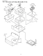
Page 74: ...74 BL C111A BL C131A 16 3 Accessories and Packing Materials BL C111A ...

Page 75: ...75 BL C111A BL C131A 16 4 Accessories and Packing Materials BL C131A ...

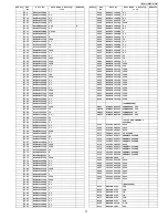
Page 76: ...W1 CABINET COVER ABS V0 11 PSME1009Z COVER 12 PSHX1232Z SPACER 13 PSHR1337Z ANGLE BOARD SUPPORT POM HB 14 PQMG10032Z RUBBER PARTS 15 PSHA1014Z RUBBER PARTS 16 PSHR1335Z SPACER 17 PQGT19330Z NAME PLATE 18 PSQT2112Z LABEL 19 PQQT23322Z LABEL 20 PQHG10751Z BOARD SUPPORT RUBBER 21 PSHR1323Y GUIDE PAN GEAR POM HB 22 PSHX1236Z SPACER 23 PSKE1074Z2 EYE LEFT COVER ABS V0 24 PSKV1043Z2 EYE CENTER COVER ABS...

Page 77: ... 0 1 C202 ECUE1C104ZFQ 0 1 C203 ECUE1C104ZFQ 0 1 Safety Ref No Part No Part Name Descrip tion Remarks C204 ECUE1C104ZFQ 0 1 C206 ECUE1C104ZFQ 0 1 C208 ECUE1C104ZFQ 0 1 C209 F1J0J1060006 10 C240 ECUE1H221JCQ 220P C251 ECUE1C104ZFQ 0 1 C252 ECUE1C104ZFQ 0 1 C258 ECUE0J105KBQ 1 C259 ECUE1C104ZFQ 0 1 C260 ECUE1C104ZFQ 0 1 C261 F1J0J1060006 10 C402 ECUE1C104ZFQ 0 1 C404 ECUE1C104ZFQ 0 1 C414 ECUE1C104Z...

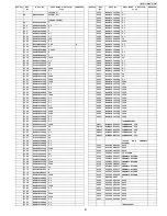
Page 78: ...RRAY SWITCHES SW201 K0D122A00098 SWITCH CRYSTAL OSCILLATORS X101 H0J480500028 CRYSTAL OSCILLATOR X201 H0J250500061 CRYSTAL OSCILLATOR Safety Ref No Part No Part Name Descrip tion Remarks PCB2 PQWP2C111A LENS BOARD ASS Y RTL Safety Ref No Part No Part Name Descrip tion Remarks Safety Ref No Part No Part Name Descrip tion Remarks PCB3 PQWP3C111A I O BOARD ASS Y RTL ICS IC1 B1DHCD000018 TRANSISTOR SI...

Page 79: ...C855 F1J0J1060006 10 C856 ECUV1A224KBV 0 22 C857 ECUV1E104ZFV 0 1 C858 ECUV0J105KBV 1 S C860 ECUV0J105KBV 1 S C861 ECUV0J105KBV 1 S C862 ECUE1H100DCQ 10P C863 ECUV0J105KBV 1 S C864 ECUV1C473KBV 0 047 C865 ECUV0J105KBV 1 S C866 ECUV0J105KBV 1 S C867 ECUV1H331JCV 330P C868 ECUE1H100DCQ 10P C869 F1J0J1060006 10 C870 ECUV1E104ZFV 0 1 C871 ECUV1C474KBV 0 47 C872 ECUV1H122KBV 0 0012 C873 ECUV0J105KBV 1 ...

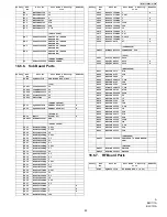
Page 80: ...INET BODY ABS V0 52 PSMH1291Z ANGLE 53 PSKF1087W1 CABINET COVER ABS V0 54 PSBD1017Z1 KNOB 55 PSHA1014Z RUBBER PARTS 56 PQGT19446Z NAME PLATE 57 PSQT2112Z LABEL 58 PQQT23346Z LABEL 59 PSQA2830Z LABEL 60 PQMG10032Z RUBBER PARTS 61 PSHR1323Y GUIDE PAN GEAR POM HB 62 PSHX1236Z SPACER 63 PSKE1074Z2 EYE LEFT COVER ABS V0 64 PSKV1043Z2 EYE CENTER COVER ABS V0 65 PSKE1075Z2 EYE RIGHT COVER ABS V0 66 PSME1...

Page 81: ...104ZFQ 0 1 Safety Ref No Part No Part Name Descrip tion Remarks C193 ECUV1C105ZFV 1 C194 ECUE1C104ZFQ 0 1 C196 ECUE1C104ZFQ 0 1 C200 ECUE1C104ZFQ 0 1 C201 ECUE1C104ZFQ 0 1 C202 ECUE1C104ZFQ 0 1 C203 ECUE1C104ZFQ 0 1 C204 ECUE1C104ZFQ 0 1 C206 ECUE1C104ZFQ 0 1 C208 ECUE1C104ZFQ 0 1 C209 F1J0J1060006 10 C240 ECUE1H221JCQ 220P C251 ECUE1C104ZFQ 0 1 C252 ECUE1C104ZFQ 0 1 C258 ECUE0J105KBQ 1 C259 ECUE1...

Page 82: ...OR ARRAY RA151 D1H84704A024 RESISTOR ARRAY RA152 D1H84704A024 RESISTOR ARRAY RA153 D1H84704A024 RESISTOR ARRAY RA401 D1H82214A024 RESISTOR ARRAY RA402 D1H82214A024 RESISTOR ARRAY SWITCHES SW201 K0D122A00098 SWITCH SW202 K0D122A00098 SWITCH Safety Ref No Part No Part Name Descrip tion Remarks CRYSTAL OSCILLATORS X101 H0J480500028 CRYSTAL OSCILLATOR X201 H0J250500061 CRYSTAL OSCILLATOR Safety Ref No...

Page 83: ...60006 10 C854 ECUV1E104ZFV 0 1 C855 F1J0J1060006 10 C856 ECUV1A224KBV 0 22 C857 ECUV1E104ZFV 0 1 C858 ECUV0J105KBV 1 S C860 ECUV0J105KBV 1 S C861 ECUV0J105KBV 1 S C862 ECUE1H100DCQ 10P Safety Ref No Part No Part Name Descrip tion Remarks C863 ECUV0J105KBV 1 S C864 ECUV1C473KBV 0 047 C865 ECUV0J105KBV 1 S C866 ECUV0J105KBV 1 S C867 ECUV1H331JCV 330P C868 ECUE1H100DCQ 10P C869 F1J0J1060006 10 C870 E...

Reviews: