background image


„

Shoot under the proper lighting conditions.

To produce pictures with eye-pleasing colors, shoot under the 

proper lighting conditions.

The pictures may not appear with their proper colors when shooting 

under fluorescent lights. Select the proper lighting as required.


„

To ensure a stable performance in the long 

term

Using the unit for prolonged periods in locations where the 

temperature and humidity levels are high will cause its parts 

to deteriorate, resulting in a reduction of its service life. 

(Recommended temperature: Max. 35°C [95°F])

Ensure that a cooling unit or heating unit will not blow any air 

directly toward the installation location.


„

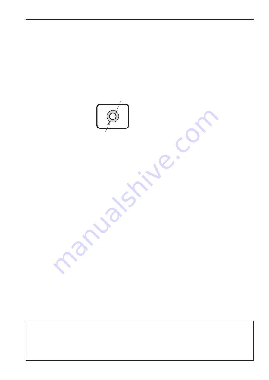
Do not point the camera at 

strong lights.

When parts of the MOS sensor are 

exposed to spotlights or other strong 

lights, blooming (a phenomenon where 

the edges of strong lights become 

blurred) may occur.

Bright subject

Blooming


„

What happens with high-brightness subjects

Flare may occur if an extremely bright light source is pointed at 

the lens. In a case like this, change the angle or take some other 

remedial action.


„

Operating temperature range

Avoid using the unit in cold locations where the temperature drops 

below 0°C (32°F) or hot locations where the temperature rises 

above 40°C (104°F) since these temperatures downgrade the 

picture quality and adversely affect the internal parts.

Furthermore, it may take a few minutes for images to stabilize when 

the unit is used at low temperatures. We recommend turning the 

unit on to let it warm up for a while before use.


„

Concerning PoE power supply

The unit complies with the IEEE802.3af standard. Use a compatible 

Ethernet hub and PoE injector to use a PoE power supply.

For details on Ethernet hubs and PoE injectors for which operations 

have been verified, consult your local dealer.


„

Turn off the unit before connecting or 

disconnecting the cables.

Be sure to turn off the equipment before connecting or 

disconnecting the cables.


„

Handle the unit carefully.

Do not drop the unit or subject it to strong impact or vibration. 

Failure to obey may cause the unit to malfunction.


„

When the unit is not in use

Turn off the unit when it will not be used.

When the unit is no longer going to be used, do not leave it lying 

around, but be absolutely sure to dispose of it properly.


„

Do not touch the optical system parts.

The optical system parts are vital to the operation of the camera. 

Under no circumstances must they be touched. In the unlikely event 

that they have become dusty, remove the dust by using a camera 

blower or by wiping them gently with a lens cleaning paper.


„

Do not point the camera directly at the sun or a 

laser beam no matter whether it is turned on or 

not.

Taking images of the sun, laser beams, or other brightly lit subjects 

for prolonged periods of time may damage the MOS sensor.


„

Do not use for long periods of time.

Use for long periods of time may cause heat to build up inside, 

resulting in a failure.


„

Personal computer used

If the same image is displayed for a prolonged period on a PC 

monitor, the monitor may be damaged. Use of a screen saver is 

recommended.


„

Concerning the IP address setting

Do not use Easy IP Setup Software on multiple personal computers 

to set the IP address for one camera at the same time.

Doing so may result in no longer knowing what IP address is set.


„

Keep the unit away from water.

Avoid all direct contact with water. Failure to obey may cause the 

unit to malfunction.


„

Maintenance

Turn off the unit’s power before proceeding with maintenance. 

Failure to obey may result in injuries.

Wipe the surfaces using a soft dry cloth. Avoid all contact with 

benzine, paint thinners and other volatile substances, and avoid 

using these substances. Otherwise, the casing may become 

discolored.


„

Use the unit in an environment with minimal 

moisture and dust.

Avoid using the unit in an environment with high concentration of 

moisture or dust since these conditions will damage the internal 

parts.


„

Disposal of the unit

When the unit has reached the end of its service life and is to be 

disposed of, ask a qualified contractor to dispose of the unit properly 

in order to protect the environment.

Operating precautions


„

Information on software used with this product

This product includes GNU General Public License (GPL) and GNU Lesser General Public License (LGPL) licensed software, and the customer is 

entitled to obtain, modify, or redistribute the source code for the software.

For details on obtaining the source codes, visit the following website.

http://pro-av.panasonic.net/

However, do not contact Panasonic for questions regarding obtained source codes.

10

11

Summary of Contents for AW-HEA10WPJ

Page 1: ...plied Installation Instructions Model No AW HEA10WPJ Model No AW HEA10KPJ Model No AW HEA10WEJ Model No AW HEA10KEJ Model No AW HEA10WP Model No AW HEA10KP Operating Instructions Control Assist Camera...

Page 2: ...l children CAUTION This apparatus can be operated at a voltage in the range of 100 240 V AC Voltages other than 120 V are not intended for U S A and Canada Operation at a voltage other than 120 V AC m...

Page 3: ...3 Heed all warnings 4 Follow all instructions 5 Do not use this apparatus near water 6 Clean only with dry cloth 7 Do not block any ventilation openings Install in accordance with the manufacturer s i...

Page 4: ...nce use the recommended accessories only CAUTION Check the installation at least once a year An improper installation could cause the unit to fall off resulting in personal injury CAUTION Do not pick...

Page 5: ...shielded cables which provide quality performance for high frequency applications as connecting cables When connecting to the DVI signal terminal use a cable with a ferrite core If your apparatus is s...

Page 6: ...pressly prohibited Abbreviations The following abbreviations are used in this manual Microsoft Windows 7 Professional SP1 32 bit 64 bit is abbreviated to Windows 7 Microsoft Windows 8 Pro 32 bit 64 bi...

Page 7: ...as with the PTZ Cntrl app 14 Installing PTZ Cntrl 14 Connecting with the iPad 14 Configuring the initial settings of PTZ Cntrl 14 Controlling the cameras with PTZ Cntrl 15 Displaying the web screen 16...

Page 8: ...s provided by Panasonic Corporation Download the app from App StoreSM 2 Power over Ethernet Referred to as PoE in this manual 3 For details on PoE devices for which operation has been verified consult...

Page 9: ...such as those described below to protect yourself against the above network security risks Use the unit in a network secured by a firewall etc If the unit is connected to a network that includes perso...

Page 10: ...AW HEA10WEJ KEJ WP KP 2 types For areas other than the U K For the U K Drop prevention wire 1 Drop prevention wire mounting screw M4x8 mm 1 Mounting bracket A for mounting this unit 1 Mounting bracket...

Page 11: ...o not leave it lying around but be absolutely sure to dispose of it properly Do not touch the optical system parts The optical system parts are vital to the operation of the camera Under no circumstan...

Page 12: ...it is on will initialize the user management settings and network settings Initialize the settings as described below 1 Close the camera menu and Web setup screen 2 Press the INIT button 3 Turn the un...

Page 13: ...nic HD integrated camera e g AW HE130 AW HE40 that you will use in conjunction with this unit or download it from the following website http pro av panasonic net z zEasy IP Setup Software EasyIPSetup...

Page 14: ...Group screen opens 4 Tap Add Group and then tap Add Camera of the Camera Group items 5 Tap the model name of the connected HD integrated camera and configure the IP addresses for PTZ Camera and Sub Ca...

Page 15: ...of the screen or pinch 1 the upper area of the screen You can also tap the camera image in the upper area of the screen to move the center of the image to the tapped position or drag the image to cont...

Page 16: ...ari 1 screens 1 There may be differences in some parts of the screen displays 1 Start the Web browser and then enter http Unit s IP address in the address bar If the unit s IP address has been changed...

Page 17: ...it Standby Switch the unit to standby mode NOTE Before turning on the unit turn on all connected devices After switching the unit to standby mode turn off all connected devices 4 Main area IP video di...

Page 18: ...r in manual mode This is disabled in auto mode NOTE Contrast Level and Back Light COMP cannot be set in manual mode 8 Image resolution list box Image Resolution Change the resolution of live images 64...

Page 19: ...main area User mng screen page 23 6 Network button Network Click this button to display the Network screen in the main area Network screen page 24 7 Maintenance button Maintenance Click this button t...

Page 20: ...memory and configure system settings and other settings The screen consists of two tabs Image and System Image screen Display the image quality adjustment screen or preset position screen To display...

Page 21: ...DRS This enables the dynamic range to be expanded by compressing the video signal level of the highly illuminated areas that get washed out with standard recording Setting values Off On Factory settin...

Page 22: ...shooting in a location that is too dark light Make the images darker in manual mode This is disabled in auto mode Make the images brighter in manual mode This is disabled in auto mode NOTE Contrast L...

Page 23: ...type password and Access level and then click Set User auth Set whether or not to perform user authentication when the Web screen opens Click Set to complete the setting Setting values On Perform user...

Page 24: ...s subnet mask when the DHCP function will not be used Factory setting 255 255 255 0 Default gateway Enter the unit s default gateway when the DHCP function will not be used Factory setting 192 168 0 1...

Page 25: ...gure the display settings To display the Other screen click the Other tab in the Maintenance screen Reset to the default Except the network settings Restore the unit s settings to the initial settings...

Page 26: ...reset position to open the Preset position screen 2 Select any of 1 to 9 from the pull down menu of Preset 3 Click Set The current setting conditions are registered to the preset memory If there are s...

Page 27: ...Refer to the operating instructions for the PoE power supply device Installation Instructions Web screen Symptom Cause and solution Reference pages Web screen cannot be accessed Check the system requ...

Page 28: ...es check box and then click Delete 4 Click the OK button For Mac 1 Select Safari Empty Cache in Safari 2 Click Empty in the Are you sure you want to empty the cache pop up screen If Check for newer ve...

Page 29: ...et the pop up to Always allow 1 Click Options for this site in the information bar 2 Click Always allow B Register as trusted site and add security setting 1 Click Tools Internet options in Internet E...

Page 30: ...nt window may be displayed and another pop up window may open Screen layout is abnormal portions of the screens do not appear when running Compatibility View or a pop up screen concerning the inabilit...

Page 31: ...x Minimum illumination Approx 20 lx 1 60 in auto mode Video output HDMI HDMI connector HDCP is not supported Viera Link is not supported Network 10BASE T 100BASE TX RJ 45 connector Automatic recogniti...

Page 32: ...23 IR ID 23 L LAN connector 12 Lens 12 Live 17 19 Live screen 17 M MAC address 25 Main area 17 19 Maintenance 19 25 microSD card slot 12 Model no 25 N Network 19 24 O Operation time 25 Optional acces...

Page 33: ...33 MEMO...

Page 34: ...proper treatment recovery and recycling of old products please take them to applicable collection points in accordance with your national legislation By disposing of them correctly you will help to sa...

Reviews: