background image

Frame Mix

Select for frame addition (gain-up using sensor storage) amount.

When frame addition is performed, it will appear as if the images are 

missing some frames.

Setting value:

 Off / 6dB / 12dB / 18dB / 24dB

Factory settings:

 Off

• This cannot be configured when the format is 1080/29.97p, 

1080/23.98p, 1080/29.97PsF, 1080/23.98PsF, 1080/25p, or 

1080/25PsF.

• [Frame Mix] cannot be set to [18dB] or [24dB] when [Iris Mode], 

[Gain], or [Focus Mode] is set to [Auto]. (When setting [Frame Mix] 

to [18dB] or [24dB], set [Iris Mode] and [Focus Mode] to [Manual] 

and set [Gain] to any setting other than [Auto].)

<NOTE>

• Under discharge tube illumination, such as fluorescent and mercury-

vapor lights, the brightness may change synchronously, colors may 

change, and horizontal stripes may flow up and down the image.

In such cases, we recommend setting the electronic shutter speed 

to 1/100 in regions with 50 Hz power supply frequency, and to OFF 

in regions with 60 Hz power supply frequency.

ND Filter

Set the transmittance of the lens’ built-in ND (neutral density) filter.

Setting value:

Through

Do not set ND filter.

1/8

Set ND filter transmittance to 1/8.

1/64

Set ND filter transmittance to 1/64.

Factory settings:

 Through

Day/Night

Switch between standard shooting and night-vision shooting (shooting 

with infrared light).

Setting value:

Day

Standard shooting (day mode)

Night

Night-vision shooting (night mode)

Factory settings:

 Day

<NOTE>

• The iris will be forcibly opened.

• White balance adjustment is not possible in night mode.

• ND filter switching is not possible in night mode.

• Pedestal adjustment is not possible in night mode.

Picture

78

Web screen configurations  (continued)

79

Summary of Contents for AW-HE130KP

Page 1: ...ad the instructions carefully and save this manual for future use z zAbout the instruction manuals Operating Instructions this document This manual describes how to operate and configure settings for the unit Installation Instructions This manual includes information on installation and system configurations for the unit Be sure to read this before installing the unit to ensure proper installation...

Page 2: ...nfants and small children CAUTION This apparatus can be operated at a voltage in the range of 100 240 V AC Voltages other than 120 V are not intended for U S A and Canada Operation at a voltage other than 120 V AC may require the use of a different AC plug Please contact either a local or foreign Panasonic authorized service center for assistance in selecting an alternate AC plug CAUTION The mains...

Page 3: ...Heed all warnings 4 Follow all instructions 5 Do not use this apparatus near water 6 Clean only with dry cloth 7 Do not block any ventilation openings Install in accordance with the manufacturer s instructions 8 Do not install near any heat sources such as radiators heat registers stoves or other apparatus including amplifiers that produce heat 9 Do not defeat the safety purpose of the polarized o...

Page 4: ...perable The AC receptacle mains socket outlet shall be installed near the equipment and shall be easily accessible To completely disconnect this equipment from the AC mains disconnect the power cord plug from the AC receptacle CAUTION In order to maintain adequate ventilation do not install or place this unit in a bookcase built in cabinet or any other confined space To prevent risk of electric sh...

Page 5: ... AES EBU Use shielded cables which provide quality performance for high frequency transmission applications for analog audio signals Other connecting cables IEEE1394 USB Use double shielded cables which provide quality performance for high frequency applications as connecting cables When connecting to the DVI signal terminal use a cable with a ferrite core If your apparatus is supplied with ferrit...

Page 6: ...e fuse compartment with a screwdriver Or 2 Replace the fuse Or Fuse Fuse indicates safety information Manufactured by Panasonic Corporation Osaka Japan Importer s name and address of pursuant to EU rules Panasonic Marketing Europe GmbH Panasonic Testing Centre Winsbergring 15 22525 Hamburg Germany Декларація про Відповідність Вимогам Технічного Регламенту Обмеження Використання деяких Небезпечних ...

Page 7: ...rademarks of their respective owners About copyright and licence Distributing copying disassembling reverse compiling reverse engineering and also exporting in violation of export laws of the software provided with this unit are expressly prohibited Abbreviations The following abbreviations are used in this manual Microsoft Windows 7 Professional SP1 32 64 bit is abbreviated to Windows 7 Microsoft...

Page 8: ...the operations using the wireless remote control 38 Operations on the AW RP50 Remote Camera Controller 39 Operations on the AW RP120 Remote Camera Controller 41 Operations on the AK HRP200 Remote Operation Panel 43 Camera menu items 46 Setting the camera menu items 46 Top menu Top Menu screen 46 Camera screen 47 Brightness 1 2 screen 47 Brightness 2 2 screen 48 Picture 1 3 screen 49 Picture 2 3 sc...

Page 9: ...communication format The unit is available in white AW HE130WP AW HE130WE or black AW HE130KP AW HE130KE to suit your intended application and environment Computer requirements CPU Intel Core 2 DUO 2 4 GHz or more recommended Memory For Windows 1 GB or more 2 GB or more for 64 bit editions of Microsoft Windows 8 1 Microsoft Windows 8 and Microsoft Windows 7 For Mac 2 GB or more Network function 10...

Page 10: ...BY ANY FAILURE Network security As the unit intended to be used while connected to a network the following security risks exist A Leakage or theft of information through the unit B Unauthorized operation of the unit by persons with malicious intent C Interference with or stoppage of the unit by persons with malicious intent It is your responsibility to take precautions such as those described belo...

Page 11: ... system that is even more flexible NOTE It may be necessary to upgrade the version of the controller in order to support the unit For details on upgrading visit the support page on the following website http pro av panasonic net The maximum distances between the units and controller is 1000 meters 3280 ft when serial control is exercised Use of an external device or some other means must be provid...

Page 12: ...destal B Pedestal Not supported Supported with some restrictions 5 Detail Not supported Not supported V Detail Level Not supported Not supported CAM BAR Supported 1 Supported Pan Supported Supported Tilt Supported Supported Preset Supported Supported Preset Speed Not supported Not supported Preset Speed Table Not supported Not supported Preset Scope Not supported Not supported Freeze During Preset...

Page 13: ...installation surface Hanging Desktop 1 Main unit mounting screw with flat washer spring washer M3 6 mm 1 AC adaptor 1 Power cable AW HE130WP AW HE130KP 1 1 5 m 4 9 ft AW HE130WE AW HE130KE 2 types For areas other than the U K 1 5 m For the U K 1 8 m Cable cover 1 Drop prevention wire 1 Drop prevention wire mounting screw 1 comes attached to the unit Bracket mounting screws bind head M4 10 mm 4 Opt...

Page 14: ...s provided in case the images are to be monitored Concerning the HDMI interface standard This unit has been certified as HDMI compatible but on rare occasions images may not be displayed depending on the HDMI device which has been connected to the unit Color bars Color bars are used to adjust the color phase and the widths and positions of these bars may differ from other models The setting for th...

Page 15: ...sing may become discolored Do not turn the camera head by hand Turning the camera head by hand may cause the unit to malfunction Use the unit in an environment with minimal moisture and dust Avoid using the unit in an environment with high concentration of moisture or dust since these conditions will damage the internal parts Disposal of the unit When the unit has reached the end of its service li...

Page 16: ...nit is exposed to sunlight the effects of the light may make it impossible for the unit to be operated using the wireless remote control Be sure to follow the steps below for installation and use Take steps to ensure that the wireless remote control signal light sensing area will not be exposed to the light from fluorescent lights plasma monitors or other such products or from the sun Install the ...

Page 17: ...gnal matched by the remote control ID has been received from the wireless remote control optional accessory while the power is on Orange and blinks twice When a signal not matched by the remote control ID has been received from the wireless remote control optional accessory while the power is on 6 Camera head This rotates in the up and down direction 7 Tilt head This rotates in the right and left ...

Page 18: ...video signals Use the monitor in the internal synchronization mode Provide a BNC coaxial cable as the connecting cable There is a delay in the VIDEO OUT signal output by 120H HD lines when at 720p and by 90H HD lines for any other 16 Hole used to secure cable cover Use the screw provided to secure the cable cover 17 SDI OUT connector SDI OUT This is the SDI video signal output connector 18 DC IN c...

Page 19: ...this is set to OFF the RS 422 is enabled Simultaneous output conditions for each video format z zSDI HDMI VIDEO output Format SDI output HDMI output VIDEO output HD SDI 1080 59 94p 1080 50p 1080 59 94i 1080 50i 1080 29 97psF 1080 25psF 1080 23 98psF 1080 29 97p 1 1080 25p 1 1080 23 98p 720 59 94p 720 50p SD SDI 480 59 94p 576 50p 480 59 94i 2 576 50i 2 1 Native output 2 480 59 94i and 576 50i is o...

Page 20: ...eset memory call buttons 1 to 12 These are used to call the information on the unit s directions and other settings which have been registered in the unit s preset memories No 1 to No 12 and reproduce those settings Settings in preset memories No 13 and above cannot be called from the wireless remote control 9 PRESET LIMIT button PRESET LIMIT This is used to register the settings in the preset mem...

Page 21: ...hing is not possible in night mode 15 HOME button HOME When this is pressed for 2 seconds the unit s direction panning or tilting returns to the reference position 16 ZOOM button T W These are used to adjust the lens zoom The zoom is adjusted in the wide angle using the W button and in the telephoto using the T button 17 FAST button FAST This is used to change the movement speed at which the panni...

Page 22: ...e units using wireless remote controls set a different remote control ID for each control When using one unit set the remote control ID to CAM1 unless the setting needs to be changed Setting procedure Operate the IR ID switches on the unit s rear panel and select CAM1 CAM2 CAM3 or CAM4 as the remote control ID page 18 The IR ID switch settings CAM1 to CAM4 correspond to the CAM1 to CAM4 buttons on...

Page 23: ...e same time The IP address settings may no longer be recognized as a result The Easy IP Setup Software is designed in such a way that when around 20 or more minutes have passed after the power was turned on the MAC address and IP address of the target camera will no longer be displayed For details of the display time setting refer to Easy IP Setup accommodate period page 91 The Easy IP Setup Softw...

Page 24: ...ears Follow the instructions on the screen to perform installation If direct installation from the unit is not possible due to your personal computer s settings or network environment limitations for example use the installer nwcv4SSetup exe on the supplied CD ROM If the plug in viewer software ActiveX installation screen continues to appear when switching screens even after it is installed restar...

Page 25: ...ss remote control for 2 seconds The Power ON mode is established images are output and control can be exercised The unit s status display lamp now lights up green NOTE It takes maximum 30 seconds per unit for the initial settings operation to be completed During this period the unit cannot be operated Status display lamp Lit orange 4 If a multiple number of units are going to be used repeat steps ...

Page 26: ...ss remote control the IR ID switches on the unit s back panel must be set For details of the IR ID switch settings refer to page 18 and page 22 1 Press the CAM1 CAM2 CAM3 or CAM4 button The unit s status display lamp blinks green when a signal matched by the remote control ID has been received and it blinks orange when a signal that is not matched by the remote control ID has been received When pe...

Page 27: ...shooting scene lighting and other conditions How to select the shooting mode When performing operations from a wireless remote control 2 8 4 6 7 3 5 7 1 1 Press the CAM1 CAM2 CAM3 or CAM4 button to select the unit 2 Press and hold the MENU button for about 2 seconds The Top Menu is displayed Top Menu Camera Scene Scene1 System Maintenance 3 Press the 4 or 5 button to bring the cursor to Camera 4 P...

Page 28: ... speed Press the FAST button Changing the direction or zoom at low speed Press the SLOW button The speeds at which the pan tilt zoom focus and iris are controlled are now switched When performing operations from a controller Changing the camera s direction Moving the camera toward the left or right panning Tilt the PAN TILT lever toward L or R Moving the camera up or down tilting Tilt the PAN TILT...

Page 29: ...tch the lens iris adjustment to auto Press the AUTO button of GAIN to switch the gain adjustment to auto Something is wrong with the coloring of the camera pictures Refer to Auto tracking white adjustment ATW page 33 and switch to ATW The camera menus are not displayed If any of the camera menus are displayed within less than a minute after the camera was restarted the menus will be displayed in a...

Page 30: ...rightness at the light source Manually adjusting the shutter speed The shutter speed can be set using two methods One is a method that specifies the time where a time such as 1 250 sec is designated and the other is a method that specifies the frequency where synchro scan 60 15 Hz etc is designated When shooting a TV screen or personal computer s monitor screen the horizontal noise generated when ...

Page 31: ...e preset operation for the pan tilt zoom focus or iris operation concerned will be aborted If another preset has been recalled during an ongoing preset recall the preset being recalled is aborted and operation for the preset called last is performed instead When performing operations from a wireless remote control Twelve settings preset No 1 to No 12 can be registered and called using the wireless...

Page 32: ...ew setting is entered the previous setting will be erased White balance adjustment is not possible in night mode Use the two memories to store settings corresponding to different shooting conditions Automatic adjustment AWB AWB A or AWB B When performing operations from a wireless remote control 1 Shoot a white subject such as a white wall or handkerchief so that it fills the screen Do not shoot s...

Page 33: ...ture of those objects remains unchanged However it must be reset if the color temperature changes such as when you move from indoors to outside or vice versa Auto tracking white adjustment ATW When the white balance adjustment is set to ATW the white balance continues to be adjusted automatically all the time and it is automatically corrected even when the light source or color temperature has cha...

Page 34: ... changes of the season Automatic adjustment When performing operations from a wireless remote control The procedure is identical to that of Automatic adjustment page 32 in White balance adjustment The black balance can be configured by performing automatic white balance adjustment AWB and automatic black balance adjustment ABB The white balance will also be configured so be sure to prepare the con...

Page 35: ...al 0 Return 5 Press the 4 or 5 button to bring the cursor to Pedestal Picture 1 3 Chroma Level 0 White Balance Mode AWB A Color Temperature 3200K R Gain 0 B Gain 0 Pedestal 0 R Pedestal 0 B Pedestal 0 Return 6 Press the M button to start the Pedestal value blinking 7 Press the 4 or 5 button change the Pedestal value and press the M button to enter the selection Adjust the value so that it matches ...

Page 36: ...low the operation steps in Basic setup operations page 37 to display the Top Menu 2 Press the 4 or 5 button to bring the cursor to System Top Menu Camera Scene Scene1 System Maintenance 3 Press the M button The System screen appears System Genlock Output Others Return 4 Press the 4 or 5 button to bring the cursor to Genlock and press the M button The Genlock sub menu is displayed Genlock Horizonta...

Page 37: ...splaying the Top Menu Press and hold the MENU button for about 2 seconds Press and hold the CAMERA OSD button for about 2 seconds Press and hold the CHARA MENU button for about 2 seconds Selecting items Press the 4 5 b or a button Turn the F1 dial Turn the SELECT dial Displaying sub menus Press the M button Press the F1 dial Press the SELECT dial Returning to the previous menu Place the cursor on ...

Page 38: ... a sub menu of their own 5 Press the 4 or 5 button to bring the cursor to the item to be set Each time the 4 or 5 button is pressed the cursor moves The cursor can be moved in the same way using the b or a button With the cursor at the Return position press the M button to return to the previous menu 6 Press the M button The value of the item to be set starts blinking 7 Press the 4 or 5 button to ...

Page 39: ...etting value at the lowest level 4 To exit the camera menu press and hold the CAMERA OSD for about 2 seconds Switching between day and night mode 1 Press the MENU button on the AW RP50 The MENU button lights and the PRESET MEMORY MENU buttons become selectable 2 Press the 9 SETUP button in the PRESET MEMORY MENU area The button lights and the SETUP menu appears on the LCD panel 3 Turn the F1 dial ...

Page 40: ...dial Off or On appears on the bottom right F2 area of the LCD panel 5 Turn the F2 dial to select Off or On then press the F2 dial Off Turn the optical image stabilization function off On Turn the optical image stabilization function on Digital extender setting D EXTENDER 1 Press the MENU button on the AW RP50 The MENU button lights and the PRESET MEMORY MENU buttons become selectable 2 Press the 9...

Page 41: ...the FUNCTION menu 23 button The button lights and the OPTION menu appears on the LCD panel 3 Turn the F1 dial to select FUNCTION then press the F1 dial 4 Turn the F1 dial to select OPTION Off or On appears on the bottom right F2 area of the LCD panel 5 Turn the F2 dial to select Off or On then press the F2 dial Off Day mode On Night mode Color temperature setting COLOR TEMP 1 Press the EXIT button...

Page 42: ...ton lights 2 Press the FUNCTION menu 23 button The OPTION menu appears on the LCD panel 3 Turn the F1 dial to select D EXTENDER then press the F1 dial Off or On appears on the bottom right F2 area of the LCD panel 4 Turn the F2 dial to select Off or On then press the F2 dial Off Turn the digital extender function off On Turn the digital extender function on Assigning FREEZE DURING COLOR TEMP and D...

Page 43: ...ection button Control of the selected camera is enabled For operating the camera menus When the CHARA MENU button is pressed for 2 seconds the selected camera menu is displayed overlapping the camera output image When it is pressed for 2 seconds while a camera menu is displayed the menu is exited SELECT Turn to move the cursor up and down in the camera menu or to change setting values Press to mov...

Page 44: ... switch SCENE USER FILE STORE 19 Volume lock switch VOL LOCK Supported 20 R gain volume GAIN R Supported 21 B gain volume GAIN B Supported 22 R flare pedestal volume FLARE PED PED Supported FLR 23 B flare pedestal volume FLARE PED PED Supported FLR 24 DTL volume DTL 25 Data set up DATA SET UP Supported 26 Data set down DATA SET DOWN Supported 27 Adjustment value display None Supported 28 IRIS disp...

Page 45: ...me restrictions The IRIS value cannot be displayed for 7SEG 48 Master pedestal volume M PED Supported 49 Preview switch PUSH PREVIEW 50 Fader full switch FADER FULL 51 Auto iris switch AUTO Supported 52 Iris close switch CLOSE 53 Sense volume SENSE Supported with some restrictions Used for ZOOM FOCUS SPEED adjustment 54 Coarse volume COARSE 55 Lens extender display EXT 56 Digital extender display ...

Page 46: ...the second hierarchical level is now displayed Menu items accompanied by a mark indicate data which is stored on a scene by scene basis menu items accompanied by a mark indicate data which is stored together for one camera regardless of the scenes For details on factory default settings see Camera menu item table page 60 Top menu Top Menu screen Top Menu Camera Scene Scene1 System Maintenance Came...

Page 47: ...ture level for automatic exposure compensation Its setting takes effect when Auto or ELC has been selected as the setting for any of the following automatic exposure compensation functions When Iris Mode is set to Auto When Shutter Mode is set to ELC When Gain is set to Auto Iris Mode Manual Auto This menu item is used to select whether the iris is to be adjusted automatically or manually Manual T...

Page 48: ...hen Iris Mode Gain or Focus Mode is set to Auto When setting Frame Mix to 18dB or 24dB set Iris Mode and Focus Mode to Manual and set Gain to any setting other than Auto NOTE Under discharge tube illumination such as fluorescent and mercury vapor lights the brightness may change synchronously colors may change and horizontal stripes may flow up and down the image In such cases we recommend setting...

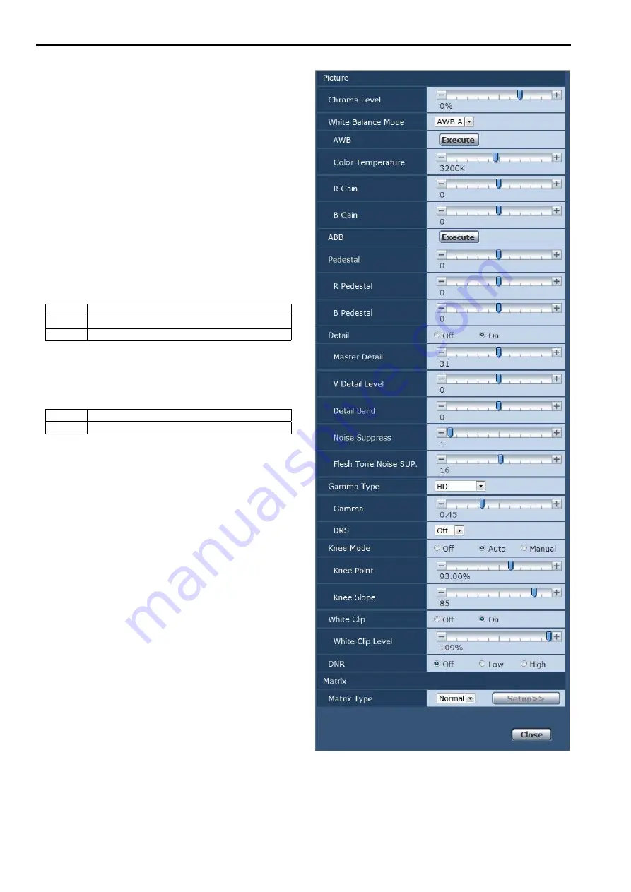
Page 49: ...elected R Pedestal 100 to 100 This enables the R pedestal to be adjusted B Pedestal 100 to 100 This enables the B pedestal to be adjusted Return Return to the previous menu level Picture 2 3 screen Picture 2 3 Detail On Master Detail 31 V Detail Level 0 Detail Band 0 Noise Suppress 1 FleshTone NoiseSUP 16 Gamma Type HD Gamma 0 45 DRS Off Return Detail Off On Turn outline i e image sharpness adjust...

Page 50: ...l 90 to 109 Set the white clip level This is only enabled when White Clip is set to On NOTE When Knee Mode is set to Auto and the white clip value is changed the knee value will also change DNR Off Low High Set the digital noise reduction level for outputting bright clear images without noise even at night and low light conditions When Low or High is selected noise can be eliminated However image ...

Page 51: ...ation Phase B_Mg 27 19 Mg 19 10 Mg_R 63 4 Mg_R_R 48 27 R 9 4 R_R_YI 62 23 Return Color Correction 1 3 This can be set when User has been selected as the Matrix Type setting Adjust the saturation and hue Saturation 63 to 63 Adjust the saturation for each color Phase 63 to 63 Adjust the hue for each color B_Mg Color between blue and magenta Mg Magenta Mg_R Color between magenta and red Mg_R_R Color ...

Page 52: ...r with a 1 3 red to yellow ratio Yl Yellow Yl_G Color between yellow and green G Green G_Cy Color between green and cyan Return Return to the previous menu level Matrix 5 5 screen Matrix 5 5 Color Correction 3 3 Saturation Phase Cy 21 8 Cy_B 15 49 B 12 3 Return Color Correction 3 3 This can be set when User has been selected as the Matrix Type setting Adjust the saturation and hue Saturation 63 to...

Page 53: ...it and operating speed as well as the settings relating to the other functions Return Return to the previous menu level Genlock screen Genlock Horizontal Phase 0 Horizontal Phase Step 1 Return Horizontal Phase 206 to 49 This is used to adjust the horizontal phase during genlock Horizontal Phase Step 1 to 10 This is selected to set the amount by which the Horizontal Phase setting is to be adjusted ...

Page 54: ...t This setting is used when the aspect ratio of the monitor is to be set to 4 3 With the vertical height serving as the reference the parts which extend beyond this at the two sides are cropped changing the view of the angle LetterBox This setting is used when the aspect ratio of the monitor is to be set to 4 3 With the horizontal width serving as the reference black bands are added at the top and...

Page 55: ...ormat The same occurs if an operation is not performed within 10 seconds If an external sync signal that does not match the changed format is input the image will be distorted Change the external sync signal or perform internal synchronization Changing the frequency When the currently selected frequency is changed in the Output screen the pre frequency change confirmation screen appears Pre freque...

Page 56: ... in conjunction with the zoom magnification When On is set the panning and tilting operations will become slower in the zoom status This function has no effect during preset operations Return Return to the previous menu level Others 2 4 screen Others 2 4 Focus Mode Auto Focus ADJ With PTZ Digital Zoom Disable Max Digital Zoom Digital Extender Off OIS Off Tally Enable Tally Brightness Low Return Fo...

Page 57: ...ra menus and statuses are not displayed on the output pictures targeted by the setting items listed above On The camera menus and statuses are displayed for the output pictures covered by the setting items listed above NOTE When this is set to Off the camera menu can be displayed for about 1 minute after the unit is turned on OSD Off With Tally Off On Off or on the function that turns off camera m...

Page 58: ...ous menu level Firmware VER 1 2 screen Firmware VER 1 2 CPU Software Interface V01 00 Camera Main V01 00 Servo V01 00 Network V01 00 EEPROM Interface V01 00 Return CPU Software Interface Display the software version of the interface CPU Software Camera Main Display the software version of the camera unit CPU Software Servo Display the software version of the servo CPU Software Network Display the ...

Page 59: ...ialize Menu settings CANCEL O K When the cursor is moved to O K on the Initialize screen and the setting is entered the Menu settings initialized screen is displayed for 5 seconds and the camera settings are restored to the settings which were established when the camera was purchased However the Format settings and Frequency settings page 54 and network settings are not initialized NOTE Operation...

Page 60: ...99 to 40 White Balance Mode AWB A AWB A AWB B ATW 3200K 5600K VAR Color Temperature 3200K 2000K to 15000K 1 R Gain 0 150 to 150 step 1 B Gain 0 150 to 150 step 1 Pedestal 0 150 to 150 step 1 R Pedestal 0 100 to 100 step 1 B Pedestal 0 100 to 100 step 1 Picture 2 3 Detail On Off On Master Detail 31 0 to 62 V Detail Level 0 7 to 7 Detail Band 0 7 to 7 Noise Suppress 1 0 to 60 FleshTone NoiseSUP 16 0...

Page 61: ... 63 R_Yl_Yl Phase 0 0 17 8 63 to 63 Yl Saturation 63 63 14 19 63 to 63 Yl Phase 29 4 7 2 63 to 63 Yl_G Saturation 17 9 0 16 63 to 63 Yl_G Phase 20 22 16 2 63 to 63 G Saturation 4 12 56 2 63 to 63 G Phase 26 4 13 4 63 to 63 G_Cy Saturation 0 0 0 0 63 to 63 G_Cy Phase 0 0 0 9 63 to 63 Matrix 5 5 Color Correction 3 3 Normal EBU NTSC User Cy Saturation 21 18 28 9 63 to 63 Cy Phase 8 24 33 5 63 to 63 C...

Page 62: ...ers 3 4 Wireless Control Enable Enable Disable OSD Mix SDI Out On Off On HDMI Out On Off On Video Out On Off On IP On Off On OSD Off With Tally Off Off On OSD Status Off Off On Others 4 4 Audio Off Off On Input Volume Line Middle Mic High Mic Middle Mic Low Line High Line Middle Line Low Plugin Power Off Off On Protocol Model Select SEVIHD1 SEVIHD1 SBRC300 SBRCZ330 Reserved1 to 7 Maintenance Firmw...

Page 63: ...st have already been installed in order to display the unit s IP videos using a personal computer which is running Windows This is not required for a personal computer which is running OS X Mac For further details refer to Installing the plug in viewer software page 24 Displaying the web screen using a personal computer The procedure is explained here using Windows screens Internet Explorer but it...

Page 64: ...ess than 14 depending on the Bandwidth control bitrate and Max bit rate per client settings A message indicating the access limit will appear if the number of users exceeds 14 When Transmission type is set to Multicast port for H 264 the second and subsequent users receiving H 264 images will not be counted toward the total access count When H 264 transmission page 73 is set to On H 264 images are...

Page 65: ...e Live screen Live Single display mode You can display images from the camera on a personal computer and perform camera operations such as pan tilt zoom and focus control The items displayed on the screen will differ depending on whether the H 264 or JPEG button is selected under Compression When H 264 is selected 3 2 4 9 1 10 11 15 12 13 14 16 18 17 20 21 19 7 8 9 1 Stream menu OSD menu When JPEG...

Page 66: ...n the Image quality JPEG settings page 73 2 When selected images appear according to the settings configured for Quality2 in the Image quality JPEG settings page 73 In the following cases the selection status of the Image quality button will return to the setting configured in the Video over IP tab Initial display settings for Live page Image quality JPEG When returning from another screen When th...

Page 67: ...PEG images will appear On a personal computer running OS X Mac regardless of the H 264 transmission settings only JPEG images will appear H 264 images will not appear When H 264 transmission is set to On the frame rate for JPEG images may drop regardless of whether H 264 images are being transmitted The speed at which the JPEG images are refreshed may be reduced depending on the network environmen...

Page 68: ...osition which is now selected on the pull down menu The settings that are reproduced at this position are the settings which were established on the Preset Scope menu page 56 page 82 page 84 The camera direction moves to the home position if Home has been selected on the pull down menu In such cases the image output during movement to the home position will not freeze regardless of the Freeze Duri...

Page 69: ... 16 sub screens 1 1 Multi Screen list box Multi screen The live screen Live display method is selected here Single The IP videos of the connected camera are displayed 4Split 4 1 Group When the cameras for multi screen display have been set ahead of time using the multi screen page 86 it is possible to view a multiple number of IP videos on a single screen Multi display mode 4Split 4 2 Group 4Split...

Page 70: ...NOTE The setting menu operations can be performed only by users whose access level is 1 Administrator For the procedure used to set the access level refer to page 87 1 3 5 2 4 6 7 8 9 1 Basic button Basic When the Basic button is pressed the Basic screen is displayed in the main area Basic screen page 71 2 Image Audio button Image Audio When the Image Audio button is pressed the Image screen is di...

Page 71: ...JKLMNOPQRSTUVWXYZ abcdefghijklmnopqrstuvwxyz Symbols _ Automatic installation of viewer software One of the following settings is selected for the automatic installation of the plug in viewer software Setting value On The plug in viewer software is automatically installed Off The plug in viewer software is not automatically installed Factory settings On Smoother live video display on the browser b...

Page 72: ...itial display settings for the Live screen Live Stream Select the type of images to display in the Live screen Live Setting value H 264 1 Display videos H 264 1 H 264 2 Display videos H 264 2 H 264 3 Display videos H 264 3 H 264 4 Display videos H 264 4 JPEG 1 Display still images JPEG 1 JPEG 2 Display still images JPEG 2 JPEG 3 Display still images JPEG 3 Factory settings H264 1 72 Web screen con...

Page 73: ... and JPEG images can be displayed on the live screen Live When On has been selected as the H 264 transmission setting the JPEG image refresh interval may become slower Internet mode over HTTP This setting is selected when transmitting H 264 images over the Internet H 264 images can be transmitted using the same broadband router settings as when transmitting JPEG images Setting value On The H 264 i...

Page 74: ...ission priority is set to Best effort specify the maximum and minimum bit rate Setting value 64kbps 128kbps 1 256kbps 1 384kbps 1 512kbps 1 768kbps 1 1024kbps 1 1536kbps 1 2048kbps 1 3072kbps 1 4096kbps 1 6144kbps 1 8192kbps 1 10240kbps 1 12288kbps 1 14336kbps 1 16384kbps 1 20480kbps 1 24576kbps 1 Factory settings H 264 1 4096kbps H 264 2 1536kbps H 264 3 1024kbps H 264 4 512kbps The range of H 26...

Page 75: ...264 3 32024 H 264 4 32034 1 The unicast port number must be configured when Transmission type is set to Unicast port MANUAL Unicast port2 Audio 1 Usable port number range 1024 to 50000 Only even numbers can be specified The port number cannot be set to 10670 Factory settings H 264 1 33004 H 264 2 33014 H 264 3 33024 H 264 4 33034 1 The unicast port number must be configured when Transmission type ...

Page 76: ...uter Setting value Mic High Set the volume to high Use this when audio is input to the camera via a microphone Mic Middle Set the volume to medium Use this when audio is input to the camera via a microphone Mic Low Set the volume to low Use this when audio is input to the camera via a microphone Line High Set the volume to high Use this when audio is input to the camera via line input Line Middle ...

Page 77: ...hutter is set to OFF Step The step shutter is set the steps can be changed Synchro The synchro shutter is set the setting can be changed continuously ELC The electronic shutter is controlled and the light quantity is adjusted automatically Factory settings Off The shutter speeds that can be set are listed below When 59 94 Hz has been set as the unit s frequency When Step is selected as the Shutter...

Page 78: ...d horizontal stripes may flow up and down the image In such cases we recommend setting the electronic shutter speed to 1 100 in regions with 50 Hz power supply frequency and to OFF in regions with 60 Hz power supply frequency ND Filter Set the transmittance of the lens built in ND neutral density filter Setting value Through Do not set ND filter 1 8 Set ND filter transmittance to 1 8 1 64 Set ND f...

Page 79: ...ce For further details refer to page 34 Pedestal This item is used to adjust the black level adjust the pedestal These parts become darker when a negative setting is selected and conversely lighter when a positive setting is selected Setting range 150 to 150 Factory settings 0 R Pedestal This enables the R pedestal to be adjusted The same R pedestal setting is used for all the scenes Setting range...

Page 80: ... compression level knee point position for high brightness video signals This is only enabled when Knee Mode is set to Manual Setting range 70 0 to 107 0 Factory settings 93 0 Knee Slope Set the knee slope This is only enabled when Knee Mode is set to Manual Setting range 0 to 99 Factory settings 85 NOTE When DRS is enabled the knee setting is disabled White Clip Turn the white clip function off o...

Page 81: ...Blue z zPreset position screen Preset position Perform operations and adjustments related to preset positions To display the Preset position screen click the Setup button for Preset position in the image adjust preset position screen Image Position The settings in this screen with the exception of Preset are applied immediately Preset This selects the preset position to be operated from the pull d...

Page 82: ...e this to select the speed at which the pan tilt zoom focus and brightness operations are to be performed Speed With Zoom POS Off or On is set here for the function used to adjust the pan tilt adjustment speed in conjunction with the zoom magnification Setting value Off The panning and tilting operations will not become slower in the zoom status On The panning and tilting operations will become sl...

Page 83: ...s to save the current position as the leftward limit Pan Right Use this to save the current position as the rightward limit Set Release Use this to enable or disable the limit setting in each direction System screen System This menu has items that relate to the genlock phase adjustment and camera s output image settings z zGenlock This item s setting is reflected immediately Horizontal Phase This ...

Page 84: ...essed Install Position Desktop or Hanging is selected here as the method used to install the unit Setting value Desktop Stand alone installation Hanging Suspended installation Factory settings Desktop When Hanging has been selected the top bottom left and right of the images will be reversed and up down left right control for panning and tilting will also be reversed Smart Picture Flip When this i...

Page 85: ... to On the digital zoom will be fixed at 1 4x When Digital Zoom is set to Enable Digital Extender is disabled Setting value Off On Factory settings Off OIS Enable or disable the optical image stabilization OIS function Setting value Off On Factory settings Off NOTE The optical image stabilization OIS function s level of correction is reduced during pan tilt operations Tally Enable or Disable is se...

Page 86: ...s Cam 1 selfcamera Cam 2 to Cam 16 Not registered NOTE When connecting via HTTPS install the security certificate for the camera to be displayed page 99 This unit is configured for cameras for which selfcamera is displayed for the IP address or host name When configuring a host name the DNS settings of the personal computer that will display the multi screen must be configured For details on the p...

Page 87: ...wser and perform access again When User auth is set to On network connection with the AW RP50 will be disabled When User auth is set to On while Authentication is set to Digest network connection with the AW RP50 AW RP120 and AK HRP200 will be disabled User name Input the user name Maximum number of characters 1 to 32 half size characters Invalid characters Factory settings blank Password Retype p...

Page 88: ...ample 192 168 0 21 1 You can delete selected hosts IP addresses by clicking the Delete button at the right Priority stream screen Priority stream Click the Priority stream tab of User mng screen User mng Selected on this screen are the settings for the priority stream which enables the images to be sent with no reduction in image quality or image refresh speed even when a multiple number of users ...

Page 89: ... 1 0 to 169 254 254 255 on the same network and configure the IP address IP address IPv4 Input the unit s IP address here when the DHCP function is not going to be used Input an address that will not duplicate an existing IP address which has been set for a personal computer or another network camera Factory settings 192 168 0 10 NOTE Multiple IP addresses cannot be used even when the DHCP functio...

Page 90: ... it is recommended that the Auto default setting be used Setting value Auto The line speed is set automatically 100 M Full 100 Mbps full duplex 100 M Half 100 Mbps half duplex 10 M Full 10 Mbps full duplex 10 M Half 10 Mbps half duplex Factory settings Auto Max RTP packet size Specify whether to limit the size of RTP packets sent from the camera when using RTP to view camera images Setting value U...

Page 91: ...ss 192 168 0 254 Enter global address from Internet port number as URL in web browser vvv xxx yyy zzz 50000 vvv xxx yyy zzz 50001 Address exchange via port forwarding vvv xxx yyy zzz 50000 192 168 0 254 50000 Address exchange via port forwarding vvv xxx yyy zzz 50001 192 168 0 254 50001 Private address 192 168 0 2 Port number 50000 Private address 192 168 0 1 Port number 50001 Recommended network ...

Page 92: ...on London Summer time daylight saving Sets whether to use summer time Selects the time zone that corresponds with the region in which the unit is going to be used Setting value In Sets the time to summer time Out Cancels summer time Auto Switches to summer time according to the start end time and date settings time day week month Factory settings Out Start time date End time date Sets the summer t...

Page 93: ...button to delete the generated self signed certificate security certificate CA Certificate Generate Certificate Signing Request When using a security certificate issued by the Certificate Authority CA as a security certificate for HTTPS a Certificate Signing Request CSR is generated for application to the Certificate Authority CA To generate a Certificate Signing Request CSR click the Execute butt...

Page 94: ...s relating to the SNMP function The status of the unit can be confirmed by connecting to it with SNMP manager To use the SNMP function consult your network administrator Community Input the name of the community to be monitored Maximum number of characters 0 to 32 half size characters Invalid characters Full size characters Factory settings blank NOTE Be sure to enter the community name when using...

Page 95: ...t page 97 4 Installing a Server Certificate page 98 2 Generating a self signed certificate page 96 When using server certificates When using self signed certificates NOTE When using a server certificate the process from applying to the Certificate Authority CA to issuing a server certificate must be performed between customers and the Certificate Authority CA Use either a self signed certificate o...

Page 96: ...and the date and time generation was completed Clicking the Apply button in Previous CRT key allows the previous CRT key to be switched to the current CRT key Generating a self signed certificate Self signed Certificate Generate NOTE A self signed certificate cannot be generated when a CRT key has not been generated 1 Click the Execute button in Self signed Certificate Generate Self signed Certifi...

Page 97: ...om Download and set to Enable 1 Click the Execute button in CA Certificate Generate Certificate Signing Request The CA Certificate Generate Certificate Signing Request dialog is displayed 2 Input information relating to the certificate to be generated Items to be entered are as follows Item Description Maximum number of characters Common Name Inputs the camera address or host name 64 half size cha...

Page 98: ... HTTPS Only HTTPS connection is possible NOTE When using an HTTPS connection network connection with the AW RP50 AW RP120 and AK HRP200 will be disabled 2 Set the Port No to be used with HTTPS in HTTPS Port Port Nos that can be selected 1 to 65535 The following port numbers are used by the unit so they cannot be used 20 21 23 25 42 53 67 68 69 80 110 123 161 162 554 995 10669 10670 59000 to 61000 ...

Page 99: ...ry time the camera is accessed even when a security certificate is installed When the security certificate is correctly installed an icon of the key will be displayed in the address bar of the web browser accessing the camera in the case of Internet Explorer 8 0 and 9 0 The screen will differ partially in the case of Internet Explorer 10 and 11 1 Accessing the Camera by HTTPS 2 When the security w...

Page 100: ...nd click OK 8 Click Next 9 Click Finish 10 Click Yes When importing is finished the Certificate was imported correctly screen is displayed 11 Click OK Closing the web browser after importing the certificate and reconnecting to it will stop the Certificate error screen being displayed 100 Web screen configurations continued ...

Page 101: ... Display the software version of the servo CPU Software Network Display the software version of the network EEPROM Interface Display the version of the setup data for the interface FPGA Lens Display the FPGA version of the lens FPGA AVIO Display the FPGA version of the AVIO FPGA Com Display the FPGA version of the communication Viewer software installation counter The number of plug in viewer soft...

Page 102: ...ce sif files CPU Software Camera Main scm files CPU Software Servo spt files CPU Software Network snw files EEPROM Interface eep files FPGA Lens fls files FPGA AVIO fav files Do not turn off the unit s power while upgrading a software version Do not turn off the power until the progress bar display is cleared While a software version is being upgraded do not attempt to execute any other operations...

Page 103: ...ownload Save the unit s settings onto the personal computer When the destination dialog box appears after clicking the Execute button specify the destination folder When Camera is selected in Config data type the following settings are saved Scene Scene1 settings Scene Scene2 settings Scene Scene3 settings Scene Scene4 settings System settings Preset settings NOTE After the Execute button is click...

Page 104: ...d 3 Live only has been selected as the access level setting Pan Tilt Zoom Preset Iris Focus Camera menu OSD menu operation If the mobile terminal does not support the character code UTF 8 the characters cannot be displayed properly When multiple Android terminals are connected to the unit at the same time operation may become unstable 1 Input http IP address mobile 1 using the mobile terminal and ...

Page 105: ...ed on the screen The characters are displayed in green for the resolution button which is currently selected The resolution configured with JPEG 1 JPEG 2 and JPEG 3 in the Video over IP tab is displayed The images are displayed with a resolution of 1920 x 1080 pixels The images are displayed with a resolution of 1280 x 720 pixels The images are displayed with a resolution of 640 x 360 pixels The i...

Page 106: ...cusing operations are displayed on the screen Use this to switch between auto and manual focusing At the auto setting focusing is performed the focal point is adjusted automatically At the auto setting the button label turns green When this is pressed while the focus is being adjusted manually the focus will be temporarily adjusted automatically It does not work during automatic adjustments Use th...

Page 107: ...e and password of an administrator or general user Depending on the mobile terminal password entry may be required when transitioning between each screen Audio cannot be received on mobile terminals If the User auth page 87 setting has been changed to On from a personal computer while the mobile terminal screen is displayed it may not be possible to refresh the mobile terminal screen In a case lik...

Page 108: ... of the self signed certificate is complete Self signed Certificate Deleted Deletion of the self signed certificate is complete Certificate Signing Request Generated Generation of the certificate signing request is complete CA Certificate Installed Installation of the server certificate is complete CA Certificate Deleted Deletion of the server certificate is complete Previous CRT key Applied The p...

Page 109: ...ons of four limiters namely the upper lower leftmost and right most limits of the travel range can be set Once they have been set the positions will not be lost even after the power has been turned off The limiters can be set or released both by the wireless remote control and controller or web setting screen Setup Whatever was set or released last takes precedence For the controller operations re...

Page 110: ...form the steps in Basic limiter operations Press the MENU button quickly and then press the b button for 2 seconds while holding down the PRESET button Setting the right most limit position of the movement range Press the b or a button of the wireless remote control to turn the unit as far as the position which will serve as the right most limit Next perform the steps in Basic limiter operations P...

Page 111: ...l no longer be acknowledged to ensure safety and prevent equipment damage Detection of equipment trouble When the unit has detected trouble its functions are shut down then the unit is restarted or the initial setting operation is performed and the normal condition of the unit is restored after about 30 seconds NOTE When trouble is detected pictures may no longer be output for a while but they wil...

Page 112: ...ote control s batteries run down or have the batteries been installed with their polarities reversed If the status display lamp does not blink even when the wireless remote control is operated near the wireless remote control signal light sensing area it means that the batteries have run down Replace the batteries Have the IR ID switches been set correctly page 18 page 22 Is there a fluorescent li...

Page 113: ...ed try following operation Reboot the unit and within 20 minutes change the IP address using the Easy IP Setup Software Has 554 been set as the HTTP port number Use any port number except for the numbers below which are used by the unit for the HTTP port number 20 21 23 25 42 53 67 68 69 110 123 161 162 554 995 10669 10670 59000 to 59999 60000 to 61000 page 90 Are you accessing via http while the ...

Page 114: ...red by the firewall or other function of the anti virus software Change the HTTP port number of the unit to a port number that will not be filtered It is not possible to download the setting files For Windows Has the file download function been disabled Perform the following A Select Tools Internet Options in Internet Explorer B Click the Security tab and click the Custom level button under Securi...

Page 115: ...l Is the URL correct Has mobile been entered at the end of the URL Check whether the URL has been entered correctly When accessing the unit from a mobile terminal mobile must be added to the end of the URL used to access the unit from a personal computer page 104 Is the HTTPS SSL encryption of the mobile terminal different from that of the unit Set HTTPS Connection for the unit to HTTP and initiat...

Page 116: ...o auto focusing Is the focus set to manual Auto focusing is initiated as soon as the focus is set to auto page 29 In some situations it may be hard to focus at the auto setting In cases like this select the manual setting and focus manually page 30 The subject is not brought into focus during zooming when the manual setting is used for the focus Was the focus adjusted at the Tele end First adjust ...

Page 117: ...screen becomes lighter With a MOS imaging sensor the pickup timing differs slightly at the top left and bottom right of the screen This means that when the flash is fired the bottom of the screen will become lighter in the field concerned and the top will become lighter in the next field This is normal and not indicative of any problem The brightness changes cyclically or the colors change and hor...

Page 118: ...red For Mac Press the Command R key on the personal computer s keyboard to request that the settings be acquired For mobile terminals Refresh the screen by pressing the Refresh button on the web browser for example to request that the settings be acquired The images do not update or display properly Perform the following to delete the temporary Internet files For Windows A Select Tools Internet Op...

Page 119: ...H 264 images images from multiple cameras appear sequentially in a single web browser For Windows This may occur depending on the combination of the personal computer s display adapter and the driver If this occurs update the first display adapter to the latest version If this does not resolve the problem adjust the hardware accelerator functon as follows This section describes the procedure for W...

Page 120: ...up exe from Panasonic System Networks Co Ltd Select Install When the security warning window appears click the Install button For Internet Explorer 8 0 The following message appears in the information bar This site might require the following ActiveX control nwcv4SSetup exe from Panasonic System Networks Co Ltd Click here to install Click the information bar and select Install ActiveX control When...

Page 121: ...trol RJ 45 RS 422 CONTROL IN RS 422A RJ 45 MIC LINE input φ3 5 mm stereo mini jack Input impedance High impedance During MIC input Supported mic Stereo mic plug in poower on off switching via menu Supply voltage 2 5 V 0 5 V Mic input sensitivity Approx 40 dBV 3 dBV 0 dB 1 V Pa 1 kHz During LINE input Input level Approx 10 dBV 3 dBV FUNCTIONS AND PERFORMANCE Camera unit Imaging sensors 1 2 86 type ...

Page 122: ...ra pan tilt head control IP connecting cable When connecting through a hub LAN cable 2 category 5e or above straight cable max 100 m 328 ft When a hub is not used LAN cable 2 category 5 or above crossover cable max 100 m 328 ft RP connecting cable LAN cable 2 category 5 or above straight cable max 1000 m 3280 ft RS 422A AW series protocol 2 Use of an STP shielded twisted pair cable is recommended ...

Page 123: ...te 93 96 D Day Night 48 78 DC IN connector 18 Default gateway 89 90 Default Gateway 59 Default reset 103 Destination IP address 1 88 Destination IP address 2 88 Detail 49 79 Detail Band 49 79 D EXTENDER 40 DHCPv6 90 Diffserv 94 Digital extender 40 Digital Extender 56 85 Digital Zoom 56 85 DNR 50 80 DNS 89 Down CONV Mode 54 84 Download 103 Drop prevention wire 17 DRS 49 80 DSCP 0 63 94 E Easy IP Se...

Page 124: ...t address 75 Multicast port 75 Multicast TTL HOP Limit 75 Multi screen 66 69 Multi Screen setup 86 N ND Filter 48 78 Network 89 Network Settings 89 Night mode 39 41 No 101 Noise Suppress 49 79 NTP 92 NTP port 92 NTP server address 92 NTP server address setting 92 O OIS 40 42 56 85 Op Lock 67 Optical image stabilization 40 42 Optional accessories 13 OSD Menu Operation 66 OSD Mix 57 85 OSD Off With ...

Page 125: ... Summer time daylight saving 92 System 46 53 83 System log 101 108 System name 94 T Tally 56 85 Tally Brightness 56 85 Tally lamp 17 107 Tilt 104 Tilt head 17 Time adjustment interval 92 Time date 101 Time zone 92 Top Menu 46 Transmission priority 73 Transmission type 75 Tripod screw holes 18 U Unicast port1 Image 75 Unicast port2 Audio 75 Updating 101 Upload 103 UPnP 92 102 User auth 87 User chec...

Page 126: ... of this product correctly will help to save valuable resources and prevent any potential negative effects on human health and the environment which could otherwise arise from inappropriate waste handling Please contact your local authority for further details of your nearest designated collection point Penalties may be applicable for incorrect disposal of this waste in accordance with national le...

Reviews: