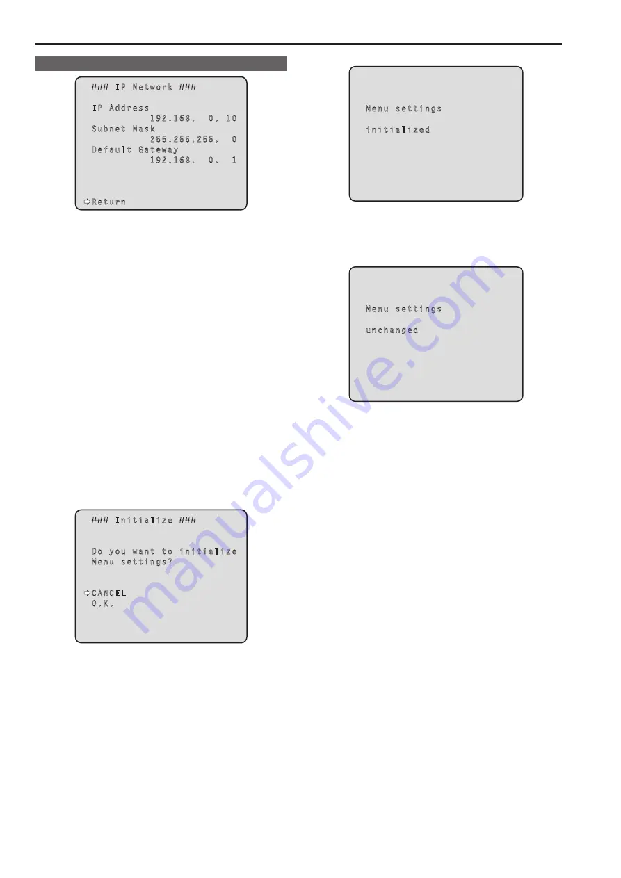
background image

IP Network screen

     IP Network 

 IP Address

           192.168.  0. 10

 Subnet Mask

           255.255.255.  0

 Default Gateway

           192.168.  0.  1

 Return

IP Address

This is selected to display the IP address which has been set for the 

unit.

Subnet Mask

This is selected to display the subnet mask which has been set for 

the unit.

Default Gateway

This is selected to display the default gateway which has been set for 

the unit.

<NOTE>

• On this screen, the [IP Address], [Subnet Mask] and [Default Gateway] 

settings can be displayed but they cannot be changed.  

To change an address, use “Network” (→page @@) on the Web 

setting screen or “Easy IP Setup Software” (→page @@).

Return

Return to the previous menu level.


„

Concerning initialization

When [Initialize] is selected on the [Maintenance] screen, the [Initialize] 

screen appears.

Initialize screen

     Initialize 

 Do you want to initialize

 Menu settings?

 CANCEL

 O.K.

• When the cursor is moved to [O.K.] on the [Initialize] screen and the 

setting is entered, the [Menu settings initialized] screen is displayed for 

5 seconds, and the camera settings are restored to the settings which 

were established when the camera was purchased.  

However, the [Format] settings and [Frequency] settings (→ page 55) 

and network settings are not initialized.

<NOTE>

• Operation returns to the Top Menu screen when the initialization 

operation is completed. At this point, set the unit to the STANDBY 

mode, and then set it to the POWER ON mode again. (See page 25)

• The [Format] and [Frequency] settings are not initialized.

• The [AWB] and [ABB] adjustment values are not initialized.

Menu settings initialized screen

 Menu settings

 initialized

• When the cursor is moved to [CANCEL] on the Initialize screen 

and the setting is entered, the [Menu settings unchanged] screen is 

displayed for 5 seconds, the initialization operation is not performed, 

and the [Maintenance] screen returns to the display.

Menu settings unchanged screen

 Menu settings

 unchanged

60

Camera menu items  (continued)

61

Summary of Contents for AW-HE130KE

Page 1: ...ully and save this manual for future use z zAbout the instruction manuals Operating Instructions this document This manual describes how to operate and configure settings for the unit Installation Instructions This manual includes information on installation and system configurations for the unit Be sure to read this before installing the unit to ensure proper installation ...

Page 2: ...quipment to rain or moisture To reduce the risk of fire or electric shock keep this equipment away from all liquids Use and store only in locations which are not exposed to the risk of dripping or splashing liquids and do not place any liquid containers on top of the equipment CAUTION This apparatus can be operated at a voltage in the range of 100 240 V AC Voltages other than 120 V are not intende...

Page 3: ...ions 2 Keep these instructions 3 Heed all warnings 4 Follow all instructions 5 Do not use this apparatus near water 6 Clean only with dry cloth 7 Do not block any ventilation openings Install in accordance with the manufacturer s instructions 8 Do not install near any heat sources such as radiators heat registers stoves or other apparatus including amplifiers that produce heat 9 Do not defeat the ...

Page 4: ...not remove panel covers by unscrewing To reduce the risk of electric shock do not remove the covers No user serviceable parts inside Refer servicing to qualified service personnel CAUTION The mains plug of the power supply cord shall remain readily operable The AC receptacle mains socket outlet shall be installed near the equipment and shall be easily accessible To completely disconnect this equip...

Page 5: ... AES EBU Use shielded cables which provide quality performance for high frequency transmission applications for analog audio signals Other connecting cables IEEE1394 USB Use double shielded cables which provide quality performance for high frequency applications as connecting cables When connecting to the DVI signal terminal use a cable with a ferrite core If your apparatus is supplied with ferrit...

Page 6: ...use need to be replaced please ensure that the replacement fuse has a rating of 13 amps and that it is approved by ASTA or BSI to BS1362 Check for the ASTA mark or the BSI mark on the body of the fuse If the plug contains a removable fuse cover you must ensure that it is refitted when the fuse is replaced If you lose the fuse cover the plug must not be used until a replacement cover is obtained A ...

Page 7: ...Note on grounding Ground the unit via the SIGNAL GND ground connector Ground connector to ground connector on wall outlet ground bar etc 7 Read this first For AW HE130WE AW HE130KE continued ...

Page 8: ...g the wireless remote control 39 Operations on the AW RP50 Remote Camera Controller 40 Operations on the AW RP120 Remote Camera Controller 42 Operations on the AK HRP200 Remote Operation Panel 44 Camera menu items 47 Setting the camera menu items 47 Top Menu screen 47 Camera screen 48 Brightness 1 2 screen 48 Brightness 2 2 screen 49 Picture 1 3 screen 50 Picture 2 3 screen 50 Picture 3 3 screen 5...

Page 9: ...e Distributing copying disassembling reverse compiling reverse engineering and also exporting in violation of export laws of the software provided with this unit are expressly prohibited Abbreviations The following abbreviations are used in this manual Microsoft Windows 7 Professional SP1 32 64 bit is abbreviated to Windows 7 Microsoft Windows 8 Pro 32 64 bit is abbreviated to Windows 8 Microsoft ...

Page 10: ...tary serial communication format The unit is available in white AW HE130W or black AW HE130K to suit your intended application and environment Computer requirements CPU Intel Core 2 DUO 2 4 GHz or more recommended Memory For Windows 1 GB or more 2 GB or more for 64 bit editions of Microsoft Windows 8 1 Microsoft Windows 8 and Microsoft Windows 7 For Mac 2 GB or more Network function 10BASE T or 10...

Page 11: ... BECAUSE THE IMAGES ENDED UP BEING USED FOR PURPOSES OTHER THAN THE ONE DESCRIBED ABOVE G LOSS OF REGISTERED DATA CAUSED BY ANY FAILURE Network security As the unit intended to be used while connected to a network the following security risks exist A Leakage or theft of information through the unit B Unauthorized operation of the unit by persons with malicious intent C Interference with or stoppag...

Page 12: ...e used together with the cameras and pan tilt head unit systems currently available from Panasonic Corporation so that an existing system can be used to advantage to put together a system that is even more flexible NOTE It may be necessary to upgrade the version of the controller in order to support the unit The maximum distances between the units and controller is 1000 meters 3280 ft when serial ...

Page 13: ...o upgrade the version of the controller in order to support the unit Consult with your dealer NOTE The following operations can not be performed via the following controllers Item AW RP400 AW CB400 AW RP555 AW RP655 Gain configuration Controller supported 13 ...

Page 14: ...yIPSetup exe Mount bracket for installation surface Hanging Desktop 1 Main unit mounting screw with flat washer spring washer M3 6 mm 1 Power cable 1 8 m 1 Drop prevention wire 1 Drop prevention wire mounting screw 1 comes attached to the unit Bracket mounting screws bind head M4 10 mm 4 Cable cover 1 AC adaptor 1 Optional accessories z zWireless remote controller AW RM50G Size AA dry battery x 2 ...

Page 15: ...elow 0 C 32 F or hot locations where the temperature rises above 40 C 104 F since these temperatures downgrade the picture quality and adversely affect the internal parts Concerning the VIDEO OUT signal The VIDEO OUT signal is provided in case the images are to be monitored Concerning the HDMI interface standard This unit has been certified as HDMI compatible but on rare occasions images may not b...

Page 16: ...hand Turning the camera head by hand may cause the unit to malfunction Use the unit in an environment with minimal moisture and dust Avoid using the unit in an environment with high concentration of moisture or dust since these conditions will damage the internal parts Disposal of the unit When the unit has reached the end of its service life and is to be disposed of ask a qualified contractor to ...

Page 17: ...nit is exposed to sunlight the effects of the light may make it impossible for the unit to be operated using the wireless remote control Be sure to follow the steps below for installation and use Take steps to ensure that the wireless remote control signal light sensing area will not be exposed to the light from fluorescent lights plasma monitors or other such products or from the sun Install the ...

Page 18: ...signal matched by the remote control ID has been received from the wireless remote control optional accessory while the power is on Orange and blinks twice When a signal not matched by the remote control ID has been received from the wireless remote control optional accessory while the power is on 6 Camera head This rotates in the up and down direction 7 Tilt head This rotates in the right and lef...

Page 19: ... the internal synchronization mode Provide a BNC coaxial cable as the connecting cable There is a delay in the VIDEO OUT signal output by 120H HD lines when at 720p and at 90H HD lines for any other 16 Hole used to secure cable cover Use the screw provided to secure the cable cover 17 SDI OUT connector SDI OUT This is the SDI video signal output connector 18 DC IN connector 12V IN Connect the AC a...

Page 20: ...nabled When this is set to OFF the RS 232C is enabled Simultaneous output conditions for each video format z zSDI HDMI VIDEO output Format SDI output HDMI output VIDEO output HD SDI 1080 59 94p 1080 50p 1080 59 94i 1080 50i 1080 29 97psF 1080 25psF 1080 23 98psF 1080 29 97p 1080 25p 1080 23 98p 720 59 94p 720 50p SD SDI 480 59 94p 576 50p 480 59 94i 1 576 50i 1 1 480 59 94i and 576 50i is output t...

Page 21: ...lled from the wireless remote control 9 PRESET LIMIT button PRESET LIMIT This is used to register the settings in the preset memories or set or release the limiters When a preset memory call button is pressed while the PRESET LIMIT button is held down the information on the unit s current direction and other settings is registered in the call button Preset memory call buttons 1 to 12 correspond to...

Page 22: ...e T button 17 FAST button FAST This is used to change the movement speed at which the panning tilting zooming and focusing operations are performed to the high speed NOTE The operating speed for panning and tilting when the preset memory settings have been called can be changed using the Preset Speed item of the camera menu 18 SLOW button SLOW This is used to change the movement speed at which the...

Page 23: ...ese units using wireless remote controls set a different remote control ID for each control When using one unit set the remote control ID to CAM1 unless the setting needs to be changed Setting procedure Operate the IR ID switch on the units rear panel and select CAM1 CAM2 CAM3 or CAM4 as the remote control ID page 19 The IR ID switch settings CAM1 to CAM4 correspond to the CAM1 to CAM4 buttons on ...

Page 24: ... designed in such a way that when around 20 or more minutes have passed after the power was turned on the MAC address and IP address of the target camera will no longer be displayed For details of the display time setting refer to Easy IP Setup accommodate period page The Easy IP Setup Software cannot be used from a different subnet via a router The unit cannot be displayed or its settings establi...

Page 25: ...ion to be completed During this period the unit cannot be operated Status display lamp light up orange 4 If a multiple number of units are going to be used repeat steps 2 and 3 as required The unit s status display lamp blinks green when a signal matched by the remote control ID has been received and it blinks orange when a signal that is not matched by the remote control ID has been received NOTE...

Page 26: ...ireless remote control the IR ID switches on the unit s back panel must be set For details of the IR ID switch settings refer to pages page 1 Press the CAM1 CAM2 CAM3 or CAM4 button The unit s status display lamp blinks green when a signal matched by the remote control ID has been received and it blinks orange when a signal that is not matched by the remote control ID has been received When perfor...

Page 27: ... shooting scene lighting and other conditions How to select the shooting mode When performing operations from a wireless remote control 2 8 4 6 7 3 5 7 1 1 Press the CAM1 CAM2 CAM3 or CAM4 button to select the unit 2 Press and hold the MENU button for about 2 seconds The Top Menu is displayed Top Menu Camera Scene Scene1 System Maintenance 3 Press the 4 or 5 button to bring the cursor to Camera 4 ...

Page 28: ...or zoom at low speed Press the SLOW button The speeds at which the pan tilt zoom focus and iris are controlled are now switched When performing operations from a controller Changing the camera s direction Moving the camera toward the left or right panning Tilt the PAN TILT lever toward L or R Moving the camera up or down tilting Tilt the PAN TILT lever toward UP or DOWN Moving the camera diagonall...

Page 29: ...k 1 Press the IRIS button several times to turn on its lamp and switch the lens iris adjustment to auto 2 Press the GAIN button several times to turn on its lamp and switch the gain adjustment to auto Something is wrong with the coloring of the camera pictures Refer to Auto tracking white adjustment ATW page 33 and switch to ATW The camera menus are not displayed If any of the camera menus are dis...

Page 30: ...re to prevent video spying Adjust the brightness at the light source Manually adjusting the shutter speed The shutter speed can be set using two methods One is a method that specifies the time where a time such as 1 250 sec is designated and the other is a method that specifies the frequency where synchro scan 60 15 Hz etc is designated When shooting a TV screen or PC monitor screen the horizontal...

Page 31: ... or iris during preset recall the preset operation for the pan tilt zoom focus or iris operation concerned will be aborted If another preset has been recalled during an ongoing preset recall the preset being recalled is aborted and operation for the preset called last is performed instead When performing operations from a wireless remote control Twelve settings preset No 1 to No 12 can be register...

Page 32: ... set it again Once a new setting is entered the previous setting will be erased Use the two memories to store settings corresponding to different shooting conditions Automatic adjustment AWB AWB A or AWB B When performing operations from a wireless remote control 1 Shoot a white subject such as a white wall or handkerchief so that it fills the screen Do not shoot shiny or very bright objects Steps...

Page 33: ... temperature of those objects remains unchanged However it must be reset if the color temperature changes such as when you move from indoors to outside or vice versa Auto tracking white adjustment ATW When the white balance adjustment is set to ATW the white balance continues to be adjusted automatically all the time and it is automatically corrected even when the light source or color temperature...

Page 34: ... changes of the season Automatic adjustment When performing operations from a wireless remote control The procedure is identical to that of Automatic adjustment page 32 in White balance adjustment The black balance can be configured by performing automatic white balance adjustment AWB and automatic black balance adjustment ABB The white balance will also be configured so be sure to prepare the con...

Page 35: ...l 0 B Pedestal 0 Return 5 Press the 4 or 5 button to bring the cursor to Pedestal Picture 1 3 Chroma Level 0 White Balance Mode AWB A Color Temperature 3200K R Gain 0 B Gain 0 Pedestal 16 R Pedestal 0 B Pedestal 0 Return 6 Press the M button to start the Pedestal value blinking 7 Press the 4 or 5 button change the Pedestal value and press the M button to enter the selection Adjust the value so tha...

Page 36: ... operation steps in Basic operations page 37 to display the Top Menu 2 Press the 4 or 5 button to bring the cursor to System Top Menu Camera Scene Scene1 System Maintenance 3 Press the M button The System screen appears System Genlock Output Others Return 4 Press the 4 or 5 button to bring the cursor to Genlock and press the M button The Genlock sub menu is displayed Genlock Horizontal Phase 0 Hor...

Page 37: ...econds Press and hold the CHARA MENU button for about 2 seconds Selecting items Press the 4 5 b or a button Turn the F1 dial Turn the F1 dial Turn the SELECT dial Displaying sub menus Press the M button Press the F1 dial Turn the F1 dial Press the SELECT dial Returning to the previous menu Place the cursor on Return and press the M button Place the cursor on Return and press the F1 dial Place the ...

Page 38: ...nu operation Unsupported controller Selecting a camera to operate Displaying the Top Menu Selecting items Displaying sub menus Returning to the previous menu Changing settings Canceling setting changes Exiting camera menu operations 38 Basic operations continued ...

Page 39: ...ave a sub menu of their own 5 Press the 4 or 5 button to bring the cursor to the item to be set Each time the 4 or 5 button is pressed the cursor moves The cursor can be moved in the same way using the b or a button With the cursor at the Return position press the M button to return to the previous menu 6 Press the M button The value of the item to be set starts blinking 7 Press the 4 or 5 button ...

Page 40: ...a setting value at the lowest level 4 To exit the camera menu press and hold the CAMERA OSD for about 2 seconds Switching between day and night mode 1 Press the MENU button on the AW RP50 The MENU button lights and the PRESET MEMORY MENU buttons become selectable 2 Press the 9 SETUP button in the PRESET MEMORY MENU area The button lights and the SETUP menu appears on the LCD panel 3 Turn the F1 di...

Page 41: ...gs OIS 1 Press the MENU button on the AW RP50 The MENU button lights and the PRESET MEMORY MENU buttons become selectable 2 Press the 9 SETUP button in the PRESET MEMORY MENU area The button lights and the USER menu appears on the LCD panel 3 Turn the F1 dial to select FUNCTION then press the F1 dial 4 Turn the F1 dial to select OIS then press the F1 dial Off or On appears on the bottom right F2 a...

Page 42: ...FUNCTION menu 29 button The button lights and the OPTION menu appears on the LCD panel 3 Turn the F1 dial to select FUNCTION then press the F1 dial 4 Turn the F1 dial to select OPTION Off or On appears on the bottom right F2 area of the LCD panel 5 Turn the F2 dial to select Off or On then press the F2 dial Off Day mode On Night mode Color temperature setting COLOR TEMP 1 Press the EXIT button and...

Page 43: ...ars on the bottom right F2 area of the LCD panel 4 Turn the F2 dial to select Off or On then press the F2 dial Off Turn optical image stabilization off On Turn optical image stabilization on Assigning FREEZE DURING and COLOR TEMP to the USER buttons You can assign the on off functions for freezing images during preset playback FREEZE DURING and color temperature settings COLOR TEMP to the USER but...

Page 44: ...ra selection button Control of the selected camera is enabled For operating the camera menus When the CHARA MENU button is pressed for 2 seconds the selected camera menu is displayed overlapping the camera output image When it is pressed for 2 seconds while a camera menu is displayed the menu is exited SELECT Turn to move the cursor up and down in the camera menu or to change setting values Press ...

Page 45: ...age switch SCENE USER FILE STORE 19 Volume lock switch VOL LOCK Supported 20 R gain volume GAIN R Supported 21 B gain volume GAIN B Supported 22 R flare pedestal volume FLARE PED PED Supported FLR 23 B flare pedestal volume FLARE PED PED Supported FLR 24 DTL volume DTL 25 Data set up DATA SET UP Supported 26 Data set down DATA SET DOWN Supported 27 Adjustment value display None Supported 28 IRIS d...

Page 46: ... IRIS Supported with some restrictions The IRIS value cannot be displayed for 7SEG 48 Master pedestal volume M PED Supported 49 Preview switch PUSH PREVIEW 50 Feder full switch FEDER FULL 51 Auto iris switch AUTO Supported 52 Iris close switch CLOSE 53 Sense volume SENSE Supported with some restrictions Used for ZOOM FOCUS SPEED adjustment 54 Coarse volume COARSE 55 Lens extender display EXT 56 Di...

Page 47: ...and indicate that the second hierarchical level is now displayed Menu items accompanied by a mark indicate data which is stored on a scene by scene basis menu items accompanied by a mark indicate data which is stored together for one camera regardless of the scenes For details on factory default settings see Camera menu item table page Top Menu screen Top Menu Camera Scene Scene1 System Maintenanc...

Page 48: ...m is selected to set the target picture level for automatic exposure compensation Its setting takes effect when Auto or ELC has been selected as the setting for any of the following automatic exposure compensation functions When Iris Mode is set to Auto When Shutter Mode is set to ELC When Gain is set to Auto Iris Mode Manual Auto This menu item is used to select whether the iris is to be adjusted...

Page 49: ...1080 23 98p 1080 29 97PsF 1080 23 98PsF 1080 25p or 1080 25PsF The auto exposure correction and auto focus functions will be disabled when Frame Mix is set to 18dB or 24dB Only manual operation will be possible NOTE Under discharge tube illumination such as fluorescent and mercury vapor lights the brightness may change synchronously colors may change and horizontal stripes may flow up and down the...

Page 50: ...is selected R Pedestal 100 to 100 This enables the R pedestal to be adjusted B Pedestal 100 to 100 This enables the B pedestal to be adjusted Return Return to the previous menu level Picture 2 3 screen Picture 2 3 Detail On Master Detail 31 V Detail Level 0 Detail Band 0 Noise Suppress 1 FleshTone NoiseSUP 16 Gamma Type HD Gamma 0 45 DRS Off Return Detail Off On This enables the B pedestal to be a...

Page 51: ... Knee Mode is set to Auto and the white clip value is changed the knee value will also change DNR Off Low High Set the digital noise reduction level for outputting bright clear images without noise even at night and low light conditions When Low or High is selected noise can be eliminated However image lag may increase Return Return to the previous menu level Matrix 1 5 screen Matrix 1 5 Matrix Ty...

Page 52: ...olor phase of the colors between blue and magenta Mg Saturation Mg Saturation 63 to 63 This is selected to increase or decrease the saturation for magenta Mg Phase Mg Phase 63 to 63 This is selected to vary the hue color phase of the magenta Mg_R Saturation Mg_R Saturation 63 to 63 This is selected to increase or decrease the saturation for colors between magenta and red Mg_R Phase Mg_R Phase 63 t...

Page 53: ... yellow and green G Saturation G Saturation 63 to 63 This is selected to increase or decrease the saturation for green G Phase G Phase 63 to 63 This is selected to vary the hue color phase of the green G_Cy Saturation G_Cy Saturation 63 to 63 This is selected to increase or decrease the saturation for colors between green and cyan G_Cy Phase G_Cy Phase 63 to 63 This is selected to vary the hue col...

Page 54: ...it and operating speed as well as the settings relating to the other functions Return Return to the previous menu level Genlock screen Genlock Horizontal Phase 0 Horizontal Phase Step 1 Return Horizontal Phase 206 to 49 This is used to adjust the horizontal phase during genlock Horizontal Phase Step 1 to 10 This is selected to set the amount by which the Horizontal Phase setting is to be adjusted ...

Page 55: ... setting is used when the aspect ratio of the monitor is to be set to 4 3 With the vertical height serving as the reference the parts which extend beyond this at the two sides are cropped changing the view of the angle LetterBox This setting is used when the aspect ratio of the monitor is to be set to 4 3 With the horizontal width serving as the reference black bands are added at the top and botto...

Page 56: ...s and confirm the display returns to the Output screen in the post change format If you move the cursor to No and confirm the display returns to the Output screen in the pre change format If an external sync signal that does not match the changed format is input the image will be distorted Change the external sync signal or perform internal synchronization Changing the frequency When the currently...

Page 57: ...unction used to adjust the pan tilt adjustment speed in conjunction with the zoom magnification When On is set the panning and tilting operations will become slower in the zoom status This function has no effect during preset operations Return Return to the previous menu level Other 2 4 screen Others 2 4 Focus Mode Auto Focus ADJ With PTZ Digital Zoom Disable Max Digital Zoom Digital Extender Off ...

Page 58: ...enus and statuses are not displayed on the output pictures targeted by the setting items listed above On The camera menus and statuses are displayed for the output pictures covered by the setting items listed above NOTE When this is set to Off the camera menu can be displayed for about 1 minute after the unit is turned on OSD Off With Tally Off On Enable or disable the function that turns off came...

Page 59: ...ous menu level Firmware VER 1 2 screen Firmware VER 1 2 CPU Software Interface V01 00 Camera Main V01 00 Servo V01 00 Network V01 00 EEPROM Interface V01 00 Return CPU Software Interface Display the software version of the interface CPU Software Camera Main Display the software version of the camera unit CPU Software Servo Display the software version of the servo CPU Software Network Display the ...

Page 60: ...e cursor is moved to O K on the Initialize screen and the setting is entered the Menu settings initialized screen is displayed for 5 seconds and the camera settings are restored to the settings which were established when the camera was purchased However the Format settings and Frequency settings page 55 and network settings are not initialized NOTE Operation returns to the Top Menu screen when th...

Page 61: ...to 40 White Balance Mode AWB A AWB A AWB B ATW 3200K 5600K VAR Color Temperature 3200K 2000K to 15000K 1 R Gain 0 150 to 150 step 1 B Gain 0 150 to 150 step 1 Pedestal 0 150 to 150 step 1 R Pedestal 0 100 to 100 step 1 B Pedestal 0 100 to 100 step 1 Picture 2 3 Detail On Off On Master Detail 31 0 to 62 V Detail Level 0 7 to 7 Detail Band 0 7 to 7 Noise Suppress 1 0 to 60 FleshTone NoiseSUP 16 0 to...

Page 62: ...n 63 to 63 R_Yl_Yl Phase 63 to 63 Yl Saturation 63 to 63 Yl Phase 63 to 63 Yl_G Saturation 63 to 63 Yl_G Phase 63 to 63 G Saturation 63 to 63 G Phase 63 to 63 G_Cy Saturation 63 to 63 G_Cy Phase 63 to 63 Matrix 5 5 Color Correction 3 3 Normal EBU NTSC User Cy Saturation 63 to 63 Cy Phase 63 to 63 Cy_B Saturation 63 to 63 Cy_B Phase 63 to 63 B Saturation 63 to 63 B Phase 63 to 63 Genlock Horizontal...

Page 63: ...thers 3 4 Wireless Control Enable Enable Disable OSD Mix SDI Out On Off On HDMI Out On Off On Video Out On Off On IP On Off On OSD Off With Tally Off Off On OSD Status Off Off On Others 4 4 Audio Off Off On Input Volume Line Middle Mic High Mic Middle Mic Low Line High Line Middle Line Low Plugin Power Off Off On Protocol Model Select SEVIHD1 SEVIHD1 SBRC300 SBRCZ330 Reserved1 to 7 Maintenance Fir...

Page 64: ...er software must have already been installed in order to display the unit s IP videos using a personal computer which is running Windows This is not required for a personal computer which is running MAC OS X For further details refer to Plug in viewer software Network Camera View 4S page Displaying the web screen using a personal computer The procedure is explained here using Windows screens Inter...

Page 65: ...ample is displayed Up to 14 users consisting of users receiving H 264 images and users receiving JPEG images can access the unit at the same time However the number of users that can access the unit may be less than 14 depending on the Bandwidth control bitrate and Max bit rate per client settings A message indicating the access limit will appear if the number of users exceeds 14 When Transmission...

Page 66: ...etails on the multi display mode Live screen Single display mode You can display images from the camera on a computer and perform camera operations such as pan tilt zoom and focus control The items displayed on the screen will differ depending on whether the H 264 or JPEG button is selected under Compression When H 264 is selected 1 2 3 6 7 8 9 10 14 11 12 13 15 17 16 19 20 18 When JPEG is selecte...

Page 67: ... according to the settings configured for Quality2 in the JPEG image quality settings page 5 Image Capture Size buttons These buttons appear only when JPEG images are displayed 1920 x 1080 When selected the text on the button turns green and the images in the main area appear in 1920 x 1080 size 1280 x 720 When selected the text on the button turns green and the images in the main area appear in 1...

Page 68: ...H 264 images will appear immediately after they appear on the Live screen in single display mode When it is set to Off only JPEG images will appear On a personal computer running Mac OS X regardless of the H 264 transmission settings only JPEG images will appear H 264 images will not appear When H 264 transmission is set to On the frame rate for JPEG images may drop regardless of whether H 264 ima...

Page 69: ...he preset position screen Move The camera direction moves to the preset position which is now selected on the pull down menu The settings that are reproduced at this position are the settings which were established on the Preset Scope menu page page page The camera direction moves to the home position if Home has been selected on the pull down menu 17 Scene Man 1 Select a shooting mode from the pu...

Page 70: ... 16 sub screens 1 1 Multi Screen list box Multi screen The Live screen display method is selected here Single The IP videos of the connected camera are displayed 4Split 4 1 Group When the cameras for multi screen display have been set ahead of time using the multi screen page it is possible to view a multiple number of IP videos on a single screen Multi display mode 4Split 4 2 Group 4Split 4 3 Gro...

Page 71: ...ing menu operations can be performed only by users whose access level is 1 Administrator For the procedure used to set the access level refer to page 1 3 5 2 4 6 7 8 9 1 Basic button When the Basic button is pressed the Basic screen is displayed in the main area Basic screen page 2 Image button When the Image button is pressed the Image screen is displayed in the main area Image screen page 3 Mult...

Page 72: ...efghijklmnopqrstuvwxyz Symbols _ Automatic installation of viewer software One of the following settings is selected for the automatic installation of the plug in viewer software Setting value On The plug in viewer software is automatically installed Off The plug in viewer software is not automatically installed Factory settings On Smoother live video display on the browser buffering Configure set...

Page 73: ... set the quality of the first image that appears to Quality1 or Quality2 Setting value Quality1 Image quality 1 Quality2 Image quality 2 Factory settings Quality1 z z JPEG Set the resolution and quality settings for JPEG 1 JPEG 2 and JPEG 3 For details on settings for H 264 images see page Image capture size Select the resolution of the images to be displayed when displaying JPEG images Setting va...

Page 74: ...inimum specified in Max bit rate per client according to the network bandwidth Advanced VBR Transmit H 264 images at the frame rate specified in Framerate Images will be transmitted so that the average transmission volume during the duration specified in Control time period will be the bit rate specified in Max bit rate per client Factory settings Frame rate NOTE When Transmission priority is set ...

Page 75: ...icast port AUTO Up to 24 users can access a single camera at the same time Unicast port1 Image and Unicast port2 Audio will be configured automatically when images and audio are sent from the camera We recommend selecting the Unicast port MANUAL setting when the port number transmitting the H 264 images does not need to be fixed e g during use within a network Unicast port MANUAL Up to 24 users ca...

Page 76: ...it audio data between the unit and the computer Setting value Off Do not transmit audio data between the unit and the computer All settings and controls related to audio will be disabled On The computer receives audio data from the unit This allows images to be viewed on the computer with audio Images and audio are not synchronized Factory settings Off Audio encoding format Select the compression ...

Page 77: ...ing mode from the pull down menu and click the Set button to switch to the selected mode Setting value Scene1 Scene2 Scene3 Scene4 Modes that allow you to adjust detailed settings manually for various shooting conditions and preferences Brightness Picture Level Set the target picture level for auto exposure correction This is enabled when any one of the following auto exposure correction functions...

Page 78: ...in is increased AGC Max Gain When Auto is selected as the Gain setting the maximum gain up amount can be set Setting value 6dB Set the maximum gain increase to 6 dB 12dB Set the maximum gain increase to 12 dB 18dB Set the maximum gain increase to 18 dB Frame Mix Select for frame addition gain up using sensor storage amount When frame addition is performed it will appear as if the images are missin...

Page 79: ...e balance mode which is ideal when a 3200K halogen light is used as the light source 5600K This is the white balance mode which is ideal when 5600K sunlight or fluorescent lighting is used as the light source VAR Specify a color temperature between 2000K and 15000K AWB This is used to execute automatic white balance AWB to set the white balance For further details refer to page Color Temperature S...

Page 80: ...tion level Specifying a lower value results in a subdued image The gamma curve for low brightness areas will be gentler and contrast will be sharper Specifying larger values results in an expanded gradient for dark areas and produces brighter images The gamma curve for low brightness areas will be steeper and contrast will be softer Setting range 0 30 to 0 75 DRS Set the DRS function which perform...

Page 81: ...ust the color to between 63 to 63 for each axis direction R B G R G B B R B G Color Correction Adjust the saturation and hue Saturation Adjust the saturation for each color Setting range 63 to 63 Phase Adjust the hue for each color Setting range 63 to 63 B_Mg Color between blue and magenta Mg Magenta Mg_R Color between magenta and red Mg_R_R Color with a 1 3 magenta to red ratio R Red R_R_YI Color...

Page 82: ...tomatically It does not work during automatic adjustments Far Use this to adjust the focus in the Far direction It does not work during automatic adjustments Auto Use this to switch between auto and manual focusing Brightness Use this to make the image darker It does not work during automatic adjustments Use this to make the image lighter It does not work during automatic adjustments Auto Use this...

Page 83: ...Fast Preset Speed values equivalent to the AW HE120 will be applied Preset Scope Selected here are the setting items to be recalled when the contents of the preset memory are regenerated Setting value Mode A Pan Tilt Zoom including digital zoom Focus Iris Gain white balance adjustment value Mode B Pan Tilt Zoom including digital zoom Focus Iris Mode C Pan Tilt Zoom including digital zoom Focus Fre...

Page 84: ...nitor screen the images are squeezed horizontally and extended vertically changing the view of the angle SideCut Use this when the aspect ratio of the monitor is 4 3 With the vertical height serving as the reference the parts which extend beyond this at the two sides are cropped changing the view of the angle LetterBox Use this when the aspect ratio of the monitor is 4 3 With the horizontal width ...

Page 85: ... Focus Iris Gain white balance adjustment value Mode B Pan Tilt Zoom including digital zoom Focus Iris Mode C Pan Tilt Zoom including digital zoom Focus Freeze During Preset Turn the function for freezing images during preset playback off on When this is set to On preset playback is performed with a still of the image immediately preceding the start of preset playback being output The image freeze...

Page 86: ...f On OSD Status Turn the status display during AWB and ABB on off Setting value Off On Model Select Set the protocol model for standard serial communication Do not select Reserved1 to Reserved7 Appears when the service switch SW4 at the bottom of the unit is set to ON standard serial communication Setting value SEVIHD1 SBRC300 SBRCZ330 Reserved1 to 7 Multi Screen setup screen The cameras whose ima...

Page 87: ...and mobile terminals that can access the unit Up to 24 users can be registered NOTE If user authentication fails more than 8 times within a 30 second period from the same IP address computer access to the unit will be disabled for a certain period User auth User authorization is set to On or Off here Setting value On Perform user authentication Off Do not perform user authentication Factory settin...

Page 88: ...ication Factory settings Off IP address The IP address of the personal computer from which access to the camera is allowed is input here The host name cannot be input as the IP address NOTE When the IP address subnet mask length is input the personal computers which are allowed to access the camera can be restricted on a subnet by subnet basis If for instance 192 168 0 1 24 has been input and the ...

Page 89: ...sent H 264 3 H 264 3 images are sent H 264 4 H 264 4 images are sent Factory settings JPEG 1 NOTE When Transmission priority page is set to Best effort for H 264 transmissions will occur at a variable bit rate between the maximum and minimum bit rate depending on the connection status of the other users Refresh interval Select the frame rate This is enabled only when Stream Type is set to JPEG 1 J...

Page 90: ...em administrator Factory settings Auto Primary server address Secondary server address Input the IP address of the DNS server if the Manual setting has been selected for DNS For details on the IP address of the DNS server consult your system administrator z z IPv6 network Manual Enable or disable manual configuration of the IPv6 address Setting value On Enter the IPv6 address manually Off Disable ...

Page 91: ...ompression button in the Live screen and execute SnapShot when distributing images in the smallest resolution Easy IP Setup accommodate period Select 20min or Unlimited as the time for enabling the operation of the network settings from the Easy IP Setup Software Setting value 20min The setting operations from the Easy IP Setup Software are enabled for 20 minutes after the camera has started opera...

Page 92: ...rformed here Click the links to each item to move to the respective setting page z zNTP Settings relating to the NTP server address and port No are performed here NTP server address setting Select the method to acquire the NTP server address Setting value Auto Acquires the NTP server address from the DHCP server Manual Sets the address by inputting the NTP server address in NTP server address Fact...

Page 93: ...is set to Enable page If Enable is not displayed refer to Cannot access the Internet from the Camera in the What s the Trouble section page Camera short cut Whether to create a camera short cut in the Network folder of your personal computer is set by selecting On or Off Select On to create a camera short cut To use the camera short cut function enable the UPnP function in advance in your personal...

Page 94: ...or more details refer to Setting the Connection Method page HTTPS port 1 to 65535 This sets the Port No to be used with HTTPS Port Nos that can be selected 1 to 65535 The following port numbers are used by the unit so they cannot be used 20 21 23 25 42 53 67 68 69 80 110 123 161 162 554 995 10669 10670 59000 to 61000 Factory settings 443 NOTE This unit will restart if the connection method is chan...

Page 95: ...ettings relating to the Diffserv function The Diffserv function sets the priority of image audio data transmitted from the router Priorities set to this unit must be aligned with DSCP values set to the router To use the Diffserv function consult your network administrator DSCP 0 63 Input the packet priority Maximum number of characters 0 to 63 half size characters Factory settings 0 95 Web screen ...

Page 96: ...page 4 Installing a Server Certificate page 2 Generating a self signed certificate page When using server certificates When using self signed certificates NOTE When using a server certificate the process from applying to the Certificate Authority CA to issuing a server certificate must be performed between customers and the Certificate Authority CA Use either a self signed certificate or server ce...

Page 97: ...alog allowing confirmation of the key size and the date and time generation was completed Clicking the Apply button in Previous CRT key allows the previous CRT key to be switched to the current CRT key Generating a self signed certificate Self signed Certificate Generate NOTE A self signed certificate cannot be generated when a CRT key has not been generated 1 Click the Execute button in Self sign...

Page 98: ...om Download and set to Enable 1 Click the Execute button in CA Certificate Generate Certificate Signing Request The CA Certificate Generate Certificate Signing Request dialog is displayed 2 Input information relating to the certificate to be generated Items to be entered are as follows Item Description Maximum number of characters Common Name Inputs the camera address or host name 64 half size cha...

Page 99: ...era in Connection HTTP Only HTTP connection is possible HTTPS Only HTTPS connection is possible 2 Set the Port No to be used with HTTPS in HTTPS Port Port Nos that can be selected 1 to 65535 The following port numbers are used by the unit so they cannot be used 20 21 23 25 42 53 67 68 69 80 110 123 161 162 554 995 10669 10670 59000 to 61000 Factory settings 443 3 Click the Set button The camera re...

Page 100: ...of the browser accessing the camera in the case of Internet Explorer 8 0 and 9 0 The screen will differ partially in the case of Internet Explorer 10 and 11 1 Accessing the Camera by HTTPS 2 When the security warning screen is displayed click Continue to this website not recommended screen SFV631L screen on page 166 The Live screen page is displayed When the authentication screen is displayed inpu...

Page 101: ...g screen A maximum of a hundred system logs can be stored in the unit s internal memory When this maximum number has been exceeded the old logs are overwritten successively by the new logs The logs are cleared when the unit s power is turned off No The running numbers of the system logs are displayed here Time date The times and dates when the logs were generated are displayed here The 24 hour sys...

Page 102: ...aracters 2 Click the Browse button and specify the downloaded software 3 Click the Execute button The software upgrade check screen is displayed After upgrading the software version be absolutely sure to delete the temporary Internet files NOTE Be absolutely sure to upgrade the software versions from the personal computer in the same network LAN as the unit whose firmware version is to be updated ...

Page 103: ...Execute button is clicked the unit s settings are returned to their defaults The login user name and password will also return to their defaults admin 12345 When the initialization operation is started no operations can be undertaken for about 2 minutes NOTE The following setting items will not be returned to defaults Format Frequency DHCP IP address Subnet mask Default gateway DNS HTTP port numbe...

Page 104: ... for the the destination dialog box to appear after clicking the Execute button Upload The unit s setting files which were saved in the personal computer by the download function are uploaded Click the Browse button to display the dialog box and specify the saved file When you click the OK button in the message dialog box that appears after you click the Execute button uploading starts Another mes...

Page 105: ... page 84 setting and 3 Live only has been selected as the access level setting Pan Tilt Zoom Preset Iris Focus Camera menu OSD menu operation If the mobile terminal does not support the character code UTF 8 the characters cannot be displayed properly Only one Android terminal can be connected to the unit 1 Input http IP address mobile 1 using the mobile terminal and press the enter button The unit...

Page 106: ...ls The images are displayed with a resolution of 320 x 180 pixels icon The images are displayed with a resolution of 160 x 90 pixels NOTE Depending on the resolution set for JPEG 1 JPEG 2 and JPEG 3 resolution switching may not be possible If the HTTP port number has been changed from 80 enter http IP address port number mobile 1 to specify the unit s port number When HTTPS Connection page is set ...

Page 107: ...cusing operations are displayed on the screen Use this to switch between auto and manual focusing At the auto setting focusing is performed the focal point is adjusted automatically At the auto setting the button label turns green When this is pressed while the focus is being adjusted manually the focus will be temporarily adjusted automatically It does not work during automatic adjustments Use th...

Page 108: ...ing on the mobile terminal password entry may be required when transitioning between each screen If the User auth page setting has been changed to On from a personal computer while the mobile terminal screen is displayed it may not be possible to refresh the mobile terminal screen In a case like this first close the web browser which is running on the mobile terminal and then open the mobile termi...

Page 109: ... of the self signed certificate is complete Self signed Certificate Deleted Deletion of the self signed certificate is complete Certificate Signing Request Generated Generation of the certificate signing request is complete CA Certificate Installed Installation of the server certificate is complete CA Certificate Deleted Deletion of the server certificate is complete Previous CRT key Applied The p...

Page 110: ...ns of four limiters namely the upper lower leftmost and right most limits of the travel range can be set Once they have been set the positions will not be lost even after the power has been turned off The limiters can be set or released both by the wireless remote control and controller or web setting screen Whatever was set or released last takes precedence For the controller operations refer to ...

Page 111: ...erform the steps in Basic limiter operations Press the MENU button quickly and then press the b button for 2 seconds while holding down the PRESET button Setting the right most limit position of the movement range Press the b or a button of the wireless remote control to turn the unit as far as the position which will serve as the right most limit Next perform the steps in Basic limiter operations...

Page 112: ...l no longer be acknowledged to ensure safety and prevent equipment damage Detection of equipment trouble When the unit has detected trouble its functions are shut down then the unit is restarted or the initial setting operation is performed and the normal condition of the unit is restored after about 30 seconds NOTE When trouble is detected pictures may no longer be output for a while but they wil...

Page 113: ...eb browsers Microsoft Windows 7 Professional SP1 64 bit 32 bit 1 Windows Internet Explorer 11 0 10 0 9 0 8 0 2 1 Windows XP compatibility mode is not supported 2 The 64 bit version of Internet Explorer is not supported Precautions when using Windows 7 Symptom 1 The screen layout is abnormal portions of the screens do not appear when running Compatibility View or pop up screens concerning the inabi...

Page 114: ...perate been selected properly P Cannot operate using the wireless remote control Have the remote control s batteries run down or have the batteries been installed with their polarities reversed If the status display lamp does not blink even when the wireless remote control is operated near the wireless remote control signal light sensing area it means that the batteries have run down Replace the b...

Page 115: ... shared by the unit and computer Has the Use proxy server setting been selected by the web browser When accessing the unit within the same subnet it is recommended that the unit s address be set to the Remove from proxy address When the unit and personal computer are connected to different subnets Has the wrong setting been selected as the default gateway setting for the unit P The settings on the...

Page 116: ...nternet Options in Internet Explorer B Click the Security tab and click the Custom level button under Security level for this zone C In the Security Settings dialog box select the Enable option for File download D For Internet Explorer 8 only Select the Enable option for Automatic prompting for the file downloads E Click the OK button F Click the OK button 116 Troubleshooting continued ...

Page 117: ...o manual Auto focusing is initiated as soon as the focus is set to auto P In some situations it may be hard to focus at the auto setting In cases like this select the manual setting and focus manually P The subject is not brought into focus during zooming when the manual setting is used for the focus Was the focus adjusted at the Tele end First adjust the focus at the Tele end where the focusing a...

Page 118: ...hat when the flash is fired the bottom of the screen will become lighter in the field concerned and the top will become lighter in the next field This is normal and not indicative of any problem The brightness changes cyclically or the colors change and horizontal stripes can be seen passing across the screen These phenomena flicker may occur under the illumination produced by fluorescent lighting...

Page 119: ...to the unit etc If the IP video settings of the unit were changed the image display may stop temporarily Check the level of access to the unit including the multi screen display and stop any unnecessary access Afterward check the following For Windows Press the F5 key on the computer s keyboard to request that the settings be acquired For Mac OS X Press the Command R key on the computer s keyboard...

Page 120: ...g mode of the mobile terminal enabled Disable the power saving mode of the mobile terminal to allow the images to be displayed indefinitely The tally lamps do not light Is the Tally setting set to Disable If Tally is set to Disable the unit s tally lamp does not light Change the setting to Enable Commands from the remote controller are unstable Are two or more Android terminals connected Only one ...

Page 121: ... or additional options click here Click the information bar and select Always Allow Pop ups from This Site The dialog window saying Allow pop ups from this site will be displayed Click the Yes button An unnecessary status bar or scroll bar is displayed on the pop up window Click Internet Options under Tools of the menu bar of Internet Explorer and then click the Security tab Click Internet in the ...

Page 122: ...era unit Imaging sensors 1 2 86 type Full HD 3MOS Lens Motorized 20 zoom F1 6 to F3 4 f 4 5 mm to 90 mm 35 mm equivalent 32 13 mm to 642 5 mm Focus Switching between auto and manual Focus distance Entire zooming range 800 mm 2 62 ft Wide end 400 mm 1 31 ft Color separation optical system 3MOS Minimum illumination 2 lx 50 F1 6 36 dB Horizontal resolution 1000 TV lines Typ Center area Gain selection...

Page 123: ...x 100 m 328 ft RP connecting cable LAN cable 2 category 5 or above straight cable max 1000 m 3280 ft RS 422A AW series protocol 2 Use of an STP shielded twisted pair cable is recommended Pan tilt operation speed Max 60 s Panning range 175 Tilting range 30 to 210 Depending on the pan or tilt position the camera may be reflected in the image Quietness NC35 AC adaptor Input AC 100 to 240 V 1 2 A 50 t...

Page 124: ...Index 124 ...

Page 125: ...125 MEMO ...

Page 126: ... of this product correctly will help to save valuable resources and prevent any potential negative effects on human health and the environment which could otherwise arise from inappropriate waste handling Please contact your local authority for further details of your nearest designated collection point Penalties may be applicable for incorrect disposal of this waste in accordance with national le...

Reviews: