background image

57

Chapter 5  Preparation

5

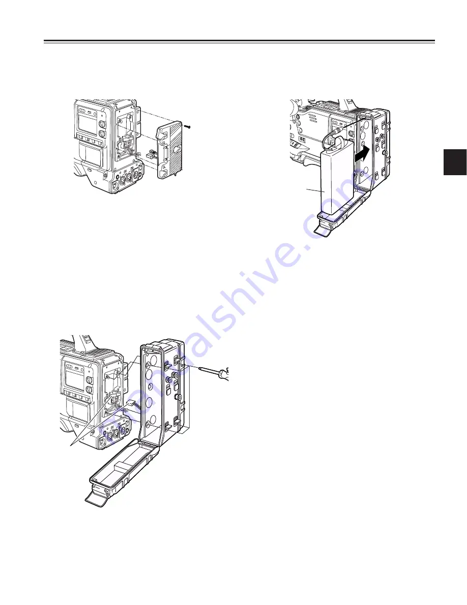
Using the battery pack made by Panasonic

1

Remove the battery holder.

Battery holder

2

Attach the battery case to the unit.

1

Connect the unit’s cable with the cable of the AU-
M402H battery case.

2

Use a screwdriver to attach the AU-M402H battery
case to the unit.
The holes for tightening the screws can be seen when
the cover is opened and the rubber caps are raised.
Use a screwdriver to tighten the screws, and attach the
battery case to the unit.  Ensure that the screws are
tightened up as far as they will go.

<Note>

Do not pull the rubber caps with great force.

Be careful not to catch up the cables when attaching the
battery case.

Connect
here.

AU-M402H
battery case

3

Connect the plug of the battery pack to the connector
inside the battery case, and insert the battery pack into
the case.

<Note>

Ensure that the power is turned off before connecting or
disconnecting the plugs.

AU-BP402
battery pack

Label
surface

4

Set the battery type.
Select the battery setting that corresponds to the battery
made by Panasonic for the BATTERY SELECT item on
the <BATTERY/TAPE> screen.  
For details, refer to “Chapter7 Menu description tables.”

Usable battery made by Panasonic:

• AU-BP402

Usable battery made by IDX:

• BP-H120

Summary of Contents for AJSDX900 - 24P DVCPRO 50

Page 1: ...Model No AJ P Operating Instructions Camera VTR Before operating this product please read the instructions carefully and save this manual for future use Printed in Japan VQT0D82 1 F0403T1073 P ...

Page 2: ...the FCC Rules These limits are designed to provide reasonable protection against harmful interference when the equipment is operated in a commercial environment This equipment generates uses and can radiate radio frequency energy and if not installed and used in accordance with the instruction manual may cause harmful interference to radio communications Operation of this equipment in a residentia...

Page 3: ...ata 31 4 5 1 Setting the user s bit 31 4 5 2 Setting the internal clock s date and time 32 4 5 3 Setting the time code 33 4 5 4 Externally locking the time code 33 4 5 5 Setting the UMID information 34 4 6 Menu displays on the viewfinder screen 35 4 6 1 Menu configuration 35 4 6 2 Basic menu operations 35 4 6 3 Selecting the user menus 36 4 7 Viewfinder screen status displays 37 4 7 1 Viewfinder l...

Page 4: ... SYSTEM SETTING 77 7 2 1 SYSTEM MODE 77 7 2 2 OPTION MODE 78 7 2 3 REC FUNCTION 78 7 2 4 OUTPUT SEL 79 7 2 5 GENLOCK 79 7 3 PAINT 80 7 3 1 ROP 80 7 3 2 MATRIX 80 7 3 3 COLOR CORRECTION 81 7 3 4 LOW SETTING 81 7 3 5 MID SETTING 82 7 3 6 HIGH SETTING 82 7 3 7 ADDTIONAL DTL 83 7 3 8 SKIN TONE DTL 83 7 3 9 KNEE LEVEL 84 7 3 10 GAMMA 84 7 3 11 FLARE 84 7 3 12 CAMERA SETTING 85 7 4 VF 85 7 4 1 VF DISPLA...

Page 5: ...ange of image expressions yielded in production Data control function When the unit is used on its own one set of user data and four sets of scene file data can be registered Further by using an SD card or a Multimedia Card optional accessory as the setup card up to eight sets of setup data can be stored Note SD card and MultiMedia card used in this unit do not comply with the SD standard Do not u...

Page 6: ...also in 5 frame increments in the 24P or 24PA mode This is quite useful when it comes to shooting programs on science or the natural world If the selection is set to the one shot recording function single frames can easily be shot NEWS REC function when AJ YA903G is not installed This function especially supports shooting in the context of news gathering or documentary filming to ensure that no op...

Page 7: ... configuration 5 inch EVF mounting adapter AJ QVF901 Battery chargers AG B425 AJ B450 SD memory cards Multimedia cards Panasonic battery AU BP402 Frame to frame continuity Simply by pressing the VTR START button or VTR button on the lens the continuity from one frame to the next is assured with a precision of 1 frame or less Rec review function This automatically rewinds the tape for the last 2 to...

Page 8: ...t fittings The shoulder belt is attached here 7 Light shoe Use this to attach the video light etc 8 Lens mount bayonet type The lens is attached to this mount 9 Lens lever This lever is tightened to secure the lens after the lens has been attached to the lens mount Lens mount cap To remove the cap push the lens lever up Keep the cap in place while the lens is not attached Lens cable microphone cab...

Page 9: ...orded W L wireless The input signals from the slot in wireless microphone receiver are recorded REAR The audio input signals supplied from the audio component which has been connected to the AUDIO IN CH1 CH2 connectors 5 are recorded 5 AUDIO IN CH1 CH2 audio input channel 1 2 connectors XLR 3 pin An audio component or microphones are connected here 6 LINE MIC 48V line input mic input mic input 48V...

Page 10: ...om the VTR MENU page by performing a menu operation MONITOR SELECT audio selection CH1 3 ST CH2 4 selector switch This is used to select the audio channels whose signals are to be output to the speaker earphone and AUDIO OUT connector in tandem with what is selected using the MONITOR SELECT switch CH1 3 The signals of audio channel 1 or 3 are output ST The stereo audio signals of either audio chan...

Page 11: ...B 3200 K C 4300 K D 6300 K ND FILTER knob inside small diameter 1 CLEAR transparent 2 1 4 ND 3 1 16 ND 4 1 64 ND Note When white balance or black balance are being automatically adjusted and the switch is pressed again to either the AWB side or to the ABB side the automatic adjustment for the side pressed will be stopped The adjusted value in this case is the value before automatic adjustment was ...

Page 12: ... USER 1 and USER 2 buttons A user setting can be allocated to each of these buttons using the setting menu When a button is pressed the user setting mode allocated to it is selected When the button is pressed again the selected mode is released Shooting and recording VTR unit AUTO KNEE function When shooting with the level set to people or scenes against a high brightness background the background...

Page 13: ...en or using a color video monitor The button s lamp comes on during playback When it is pressed during playback the unit is set to pause in the playback mode PLAY PAUSE and the button s lamp flashes If the unit is left in the pause mode for two minutes it automatically changes to the stop STOP mode D STOP button This is pressed to stop the tape travel G FF fast forward button and lamp When this bu...

Page 14: ...splay section to 00 00 00 00 If it is pressed while the TCG switch 9 is at the SET position the time code data and user s bit data are respectively reset to 00 00 00 00 6 DISPLAY switch This is used to display the time code CTL or user s bit on the counter display section depending on the setting positions of this switch and the TCG switch 9 UB The user s bit is displayed TC The time code is displ...

Page 15: ...numbers 1 and 2 indicating the audio channels appear and the CH1 and CH2 audio levels are displayed Conversely when it is set to CH3 4 numbers 3 and 4 indicating the audio channels appear and the CH3 and CH4 audio levels are displayed 1 Back tally lamp When the back tally switch 2 is set to ON this lamp serves the same function as the front tally lamp in the viewfinder 3 WARNING lamp When a proble...

Page 16: ...TC or UB is selected by the DISPLAY switch and the TC or UB generator value is displayed TC Lights when TC or UB is selected by the DISPLAY switch and the TC or UB reader value is displayed VTCG Lights when UB is selected by the DISPLAY switch and the VIUB generator value is displayed VTC Lights when UB is selected by the DISPLAY switch and the VIUB reader value is displayed TIME Lights when UB is...

Page 17: ...T control This is used to adjust the brightness of the picture seen inside the viewfinder Its adjustment does not affect the output signals of the camera ON OFF 2 8 7 1 9 3 6 4 5 7 Front tally lamp This lamp is activated when the TALLY switch 3 is set to the HIGH or LOW position and it lights while the VTR unit is recording It also flashes to provide a warning display like the REC lamp inside the ...

Page 18: ...F to turn off the unit s power Then turn the power back on and immediately hold down the EJECT button The cassette can be removed when there is still some power left in the battery However do not repeat this operation To prevent accidental erasure Set the cassette s tab to SAVE to prevent the recordings on the tape from being erased accidentally 2 Press the EJECT button The cassette holder opens 3...

Page 19: ...at least 5 segments of the remaining battery charge display are lighted If the HUMID display is showing wait until it goes off When five or more segments of the remaining battery charge display have not lighted first check the battery setting If there is nothing wrong with the battery setting replace the existing battery pack with a fully charged battery pack 3 Check that there are no cables aroun...

Page 20: ...WB position and adjust the white balance 2 Press the AUTO W B BAL switch to the ABB position and adjust the black balance 3 Press the AUTO W B BAL switch to the AWB position and adjust the white balance again For details on how to perform the adjustments refer to 4 1 1 Adjusting the white balance and 4 1 2 Adjusting the black balance 3 Point the camera at the subject and adjust the focus and zoom ...

Page 21: ...SYSTEM SETTING page by performing menu operations By controlling the VTR START button acknowledgment time during recording by up to 2 seconds the time taken for the unit to transfer from the recording mode to the rec pause mode can be delayed In other words by controlling the VTR START button operation acknowledgment time the unit can continuously record without the user having to interrupt the re...

Page 22: ...links at 5 second intervals to inform the operator Further when pause time has been set to 2 minutes or more the tally lamp blinks at 5 second intervals to indicate when recording is paused Under these conditions the tally lamp will also flash 3 seconds before recording starts A A B B C Real time video signals Real time audio signals What is recorded on the tape Previous cut PRE REC time set REC s...

Page 23: ...kpoints common to all INTERVAL REC modes Sound related Whether the sound is to be recorded or not during interval recording is set by setting ON or OFF for the AUDIO REC item on the REC FUNCTION screen Tape function button related During interval recording all the tape function buttons EJECT REW FF and PLAY STILL except STOP do not work When the unit s power was turned off during recording When AJ...

Page 24: ...ack mode REW 3 8 Rec review function When recording is temporarily stopped and the lens RET button is pressed the last two seconds of the tape are automatically rewound and the playback pictures on this part of the tape appear on the viewfinder screen This makes it possible to check whether recording was performed properly After the two seconds of the tape have been played back the unit is again s...

Page 25: ...subject may be used as a substitute for the white pattern The size of the white object required is shown in the figure below Notes Take care to keep high brightness spots off the screen Shoot white objects in the center of the screen 4 Adjust the lens aperture 5 Set the AUTO W B BAL switch to AWB and then release it The switch returns to the center and the white balance is automatically adjusted N...

Page 26: ...he function s ability to track changes in the lighting conditions and the accuracy with which the white balance is tracked For this reason handle the function carefully Viewfinder screen displays relating to the white balance For details refer to 4 7 Viewfinder screen status displays Messages relating to white balance adjustment Error message Meaning Recommended action Select a suitable filter COL...

Page 27: ... in this case is the value before automatic adjustment was performed Black balance memory The values stored in the memory are retained even after the unit s power has been turned off 4 1 2 Adjusting the black balance The black balance needs to be adjusted in the following cases When the unit is used for the first time When the unit is used after it has not been used for a prolonged period of time ...

Page 28: ... the SHUTTER SPEED screen and SHUTTER SELECT screen from the OPERATION page by performing menu operations It is now possible to restrict the shutter speed selection range to the required range beforehand and or select whether to use the SYNCHRO SCAN mode and SUPER V mode beforehand Once selected the shutter speed is retained even after the unit s power has been turned off SHUTTER SPEED SYNCHRO SCA...

Page 29: ... that V DTL be set to 0 for use In the progressive mode the shutter is forcibly set to 50 1 50 sec to produce more film like moving images To release the shutter mode it is necessary by performing menu operations to open the OPTION screen and select OFF as the P HALF SHUT item setting When the mode is switched from 60i or 30P to 24P or 24PA the images may be disrupted for an instant to adjust the ...

Page 30: ...fer to Chapter 7 Menu description tables 4 4 2 Adjusting the audio signal recording levels The procedure for manually adjusting the levels at which the signals are to be recorded on audio tracks CH1 and CH2 is set forth below 1 Set the MONITOR SELECT switch to the CH1 2 position so that the audio level meter display in the display window indicates CH1 and CH2 and check that 1 and 2 are actually in...

Page 31: ...ashing digit moves to the right UP button This increments the numerical value of the flashing digit by 1 DOWN button This decrements the numerical value of the flashing digit by 1 DISPLAY switch Display window TCG switch DOWN button UP button HOLD switch 4 4 3 CH3 and CH4 recording levels When the unit is going to be used in the DVCPRO50 format audio signals can be recorded separately for four aud...

Page 32: ...r R RUN while holding down the SHIFT button The clock is accurate to a monthly error of approximately 30 seconds in the power OFF status If a more accurate time reading is required check the time and set it again when the power is turned on When the AJ GPS900G GPS unit is installed and the time can be received the internal clock s time local date time is kept accurate on the basis of the received ...

Page 33: ...roximately 2 frames 4 5 4 Externally locking the time code The unit s internal time code generator can be locked to an external generator In addition the time code generator of an external VTR can be locked to the unit s internal generator Example of connections for external locking As the figure shows connect both the reference video signal and reference time code Example 1 When locking onto an e...

Page 34: ...ed together in the system When the signal from the unit s MON OUT connector is to be used as the reference video signal first set the OUTPUT SEL switch on the side panel to the CAM position 4 5 5 Setting the UMID information This unit supports metadata UMIDs As the UMID data the user must first set the name of his or her country with 3 or fewer characters the name of the company or organization wi...

Page 35: ...actors usually when the unit is operated by the cameraman FILE This item is used to read and write the setup card data and perform the lens file and other file related operations MAINTENANCE This item is used to perform the maintenance and inspections related to this unit s camera unit VTR MENU This item is used to perform the maintenance and inspections related to this unit s VTR unit USER MENU S...

Page 36: ...he JOG dial button in the clockwise direction as viewed from the front of the camera To decrement the value Turn the JOG dial button in the counterclockwise direction as viewed from the front of the camera Each time the button is turned the number changes by one increment When it is turned quickly the number changes quickly and when it is turned slowly the setting can be adjusted finely To set an ...

Page 37: ...ding It flashes when a problem has occurred For details refer to the appropriate section in 6 3 Warning system 3 BATT battery lamp This starts flashing when the battery voltage has dropped to the level where the battery will no longer be usable in several minutes time and it lights when the battery is no longer usable To prevent operation from being interrupted replace the battery before the batte...

Page 38: ...the color temperature is too low This warns the user that the color temperature is too high This warns the user that the brightness is too high This warns the user that the brightness is too low This warns the user that the processing could not be executed within the operation time This appears when the AWB switch has been set to PRE and AWB cannot be performed This indicates that AWB cannot be ex...

Page 39: ...hen the WHITE SHADING operation has been forcibly terminated This indicates that white shading has not been completed satisfactorily as the brightness level was excessively high during the WHITE SHADING operation This appears when the BLACK SHADING operation is ready to be performed as a result of holding down the ABB switch for a length of time during an ABB operation This appears during a BLACK ...

Page 40: ...ition This appears when the AUDIO IN switch is at the REAR position VTR warnings information REC WARNING SLACK E HUMID SERVO RF BACKUP BATT EMPTY WIRELESS RF This indicates that a problem has occurred during recording This indicates that a problem has occurred in a mechanism Depending on the nature of the trouble concerned the power may be turned off automatically Note For details on the codes dis...

Page 41: ... warning has been issued E Remaining tape min END INH Under normal conditions min lights and this starts flashing while the tape is reaching the end When the tape has reached the end END lights When recording has been inhibited INH lights C Remaining battery charge voltage V EMP MAX This indicates the remaining battery charge in 0 1V increments This indicates the remaining digital battery charge i...

Page 42: ...y type C Remaining battery charge voltage D Unit s REC display E Remaining tape F Total length of cassette tape G Super iris ON super black ON H color temperature I Shutter speed mode J D ZOOM dependent upon menu µ µ µ µ µ µ µ All input information for 4 channels µ µ µ µ µ µ µ µ µ µ µ µ µ µ µ Viewfinder screen display selection Whether a display is to be shown or not can be selected on a menu Stat...

Page 43: ...When the WHITE BAL switch setting has been changed WHITE n n ACH BCH PRESET a a When the OUTPUT AUTO KNEE switch has been set to AUTO KNEE or OFF AUTO KNEE ON or OFF a a When the shutter speed mode setting has been changed SS 1 100 or 1 120 1 250 1 500 1 1000 1 2000 S SCAN a a When the white balance AWB has been adjusted Example AWB A OK 3 2K a a When the black balance ABB has been adjusted Exampl...

Page 44: ...item as the B marker information then the 16 9 and 4 3 aspect ratios can be checked easily by operating the MARKER SELECT button as and when required 4 7 9 Checking the return video signal on the viewfinder The return video signal which has been input to the GENLOCK IN connector can be viewed in the viewfinder while the RET button on the lens is held down To activate this function perform menu ope...

Page 45: ...NG page select the VIDEO OUT signal for the VIDEO OUT SEL item select the type of characters to be superimposed onto the VIDEO OUT signal and MONITOR OUT signal for the OUTPUT CHAR item and MONITOR OUT CHAR item and select whether or not the characters are to be superimposed onto the MONITOR OUT signal When the AJ A902G expansion board is installed the SDI OUT signal can be output as the signal se...

Page 46: ...ed off The aperture is opened by a half stop The aperture is opened by a full stop The aperture is stopped down by a half stop The aperture is stopped down by a full stop No display The reference value remains unchanged S BLK The SUPER BLACK function is allocated This function reduces the black level to below the pedestal level B STR The BLACK stretch function is allocated This function highlights...

Page 47: ...and AWB B item The manual color temperature adjustment function is now valid The color temperatures are set using the COLOR TEMP PRE item COLOR TEMP A item and COLOR TEMP B item 4 9 Data handling Setup card Use of the setup memory card optional accessory enables the setting menu contents to be saved Use of this data speeds up the process of reproducing suitable setup statuses Multimedia cards or S...

Page 48: ...ottom of the viewfinder screen Note Data titles cannot be recognized when the setup card was inserted while the CARD READ WRITE screen was open Move the arrow cursor to the TITLE READ item and press the JOG dial button The data title is recognized and the title is displayed 3 When the JOG dial button is pressed the following message appears on the screen If one of the following messages appears wh...

Page 49: ...SELECT 1 READ W SELECT 1 WRITE CARD CONFIG TITLE READ TITLE 1 5 2 6 3 7 4 8 10 When the JOG dial button is pressed the arrow cursor returns to the TITLE item 11 Turn the JOG dial button to move the arrow cursor to the WRITE item 12 When the JOG dial button is pressed the following message appears 9 When the title has been input turn the JOG dial button to move the arrow cursor to the position Savi...

Page 50: ...ving is completed the following message appears 14 Press the MENU button to exit the menu operations The setting menu is cleared and the displays showing the unit s current statuses appear at the top and bottom of the viewfinder screen 4 Turn the JOG dial button to move the arrow cursor to the READ item Loading the data of the selected file CARD READ WRITE R SELECT 1 READ W SELECT 1 WRITE CARD CON...

Page 51: ... inserted Insert the card READ NG FORMAT ERROR formatting error The card was formatted by a device other than the unit Replace the card READ NG NO FILE file not found Save the file data READ NG ERROR the data cannot be loaded Data saved by devices other than unit cannot be loaded INITIALIZE READ FACTORY DATA WRITE USER DATA SCENE READ USER DATA SCENE SEL 1 READ WRITE RESET TITLE1 TITLE2 TITLE3 TIT...

Page 52: ... 4 How to use the scene file data The setting data can be written in the scene file area of the unit s internal memory and the data written can be read from this area Up to four scene files can be registered By using this data the appropriate setup statuses can be established speedily At the factory the unit s default statuses were set in TITLE1 3 and the FILM LIKE parameters were set in TITLE4 Th...

Page 53: ... stored in the scene file area of the unit s internal memory is read and the setting is completed 8 Press the MENU button to exit the menu operations 4 Press the JOG dial button to enter the scene file 5 Turn the JOG dial button to move the arrow cursor to the READ item SCENE READ USER DATA SCENE SEL 1 READ WRITE RESET TITLE1 TITLE2 TITLE3 TITLE4 Returning the setting data used for the scene files...

Page 54: ...n the following sequence Space 7 letters A Z 7 numbers 0 9 7 symbols 5 Press the JOG dial button to enter the character 6 Turn the JOG dial button to move the arrow cursor to the next position right and repeat steps 4 and 5 to set the characters maximum of 8 7 When the title has been input turn the JOG dial button to move the arrow cursor to the position SCENE READ USER DATA SCENE SEL 1 READ WRITE...

Page 55: ...ion to open the INITIALIZE screen from the FILE page 1 Set the POWER switch to the OFF position 2 Set the WHITE BAL switch to the PRST position 3 Set the POWER switch to the ON position while holding down the AUTO W B BAL switch The USER menu item settings are all returned together to the standard user data INITIALIZE READ FACTORY DATA WRITE USER DATA WHITE BAL switch 4 9 7 How to use the lens fil...

Page 56: ...ce A battery holder made by Anton Bauer is equipped with a power output connector for the lighting and a lighting control switch to enable a light to be easily attached For details on the lighting systems available contact Anton Bauer 3 Set the battery type Select the battery setting that corresponds to the battery made by Anton Bauer for the BATTERY SELECT item on the BATTERY TAPE screen For deta...

Page 57: ...up as far as they will go Note Do not pull the rubber caps with great force Be careful not to catch up the cables when attaching the battery case Connect here AU M402H battery case 3 Connect the plug of the battery pack to the connector inside the battery case and insert the battery pack into the case Note Ensure that the power is turned off before connecting or disconnecting the plugs AU BP402 ba...

Page 58: ... for the BATTERY SELECT item on the BATTERY TAPE screen For details refer to Chapter 7 Menu description tables Note When the BP 90 is to be used use the AU BP402 setting 1 Remove the battery holder 2 Attach the battery case made by Sony to the unit 1 Tighten the mounting screws 2 Tighten the power contact screws 3 Insert the top of the detached cover in the direction shown by the arrows 4 Align th...

Page 59: ...he AC adapter will rise gradually and the unit may malfunction as a result Pin no Signal 1 GND 2 3 4 12V 1 2 3 4 External DC input socket DC IN socket AC adapter AJ B75 optional accessory 5 2 Attaching the viewfinder and adjusting its position The viewfinder s position can be adjusted in the front back and left right directions so that what appears on its screen inside can be seen most easily Atta...

Page 60: ...he cable into the cable clamp and connect it to the LENS socket 3 Push down the lever for securing the lens to secure the lens LENS socket Adjusting the viewfinder s front back position 1 Loosen the viewfinder front back position anchoring ring 2 Slide the viewfinder to the front or back and adjust it to a position that allows easy viewing 3 Tighten the viewfinder front back position anchoring rin...

Page 61: ...OFF 50M INDICATOR OFF MARKER CHAR LVL 50 Adjusting the white shading of the lens The white shading is adjusted as follows Note Coloring may occur in the vertical direction near where the lens aperture is open even when the white shading has been adjusted This is something that is inherent to lenses and optical systems and is therefore not indicative of a failure or malfunctioning 2 Set the electro...

Page 62: ...NT screen select OFF as the MANUAL KNEE item setting and repeat steps 4 through 9 After W SHD OK has appeared on the display select ON again as the MANUAL KNEE item setting 14 If the extender is attached to the lens turn on the extender function or alternatively if the ratio converter is attached turn on the ratio converter function In either case repeat steps 7 through 13 The compensation values ...

Page 63: ...arrow cursor returns to the TITLE item 13 Turn the JOG dial button to move the arrow cursor to YES and press the JOG dial button When writing is complete WRITE OK is displayed indicating that the setting data and title have been stored in the lens file area of internal memory 14 Press the MENU button to exit the menu operations 4 Turn the JOG dial button to move the arrow cursor to YES and press t...

Page 64: ...n unit using the screws provided with the AJ MH700P mic holder 3 Attach the microphone to the mic holder and tighten the locking screw 4 Connect the microphone s connecting cable to the MIC IN jack on the camera 2 Attach the microphone and tighten the locking screw 3 Connect the microphone s connecting cable to the MIC IN jack on the camera 4 Set the AUDIO IN switch or switches to FRONT in accorda...

Page 65: ... switch on the rear panel to LINE 2 Align the grooves in the camera attachment with the pins on the battery case etc to attach the wireless receiver 3 Connect the AUDIO IN connectors on the camera with the wireless receiver using the XLR cable 4 Set the AUDIO IN switch or switches for the channel or channels to which the XLR cable has been connected to REAR 5 Set the LINE MIC 48V selector switch o...

Page 66: ... lever is held down Its position can be adjusted in 3 mm steps up to max of 10 steps or 30 mm in either the front or back direction While holding down the slide lever move the shoulder pad toward the front or back to the optimum shooting position Tripod attachment Slide the unit along the groove toward the front until it clicks into place Detaching the unit from the tripod attachment Red lever Whi...

Page 67: ... used rather than the shutter speeds engraved on the AJ EC3P The correspondence between the shutter speed indications on the AJ EC3P and the unit s shutter speed settings are shown in the table below 5 9 Connecting the extension control unit AJ EC3P By connecting the AJ EC3P extension control unit optional accessory some of the functions can be operated by remote control When the AJ EC3P is connec...

Page 68: ...t button point the lens at some objects with different brightness levels and check that the auto instantaneous aperture adjustment function works 6 Return the aperture to the auto adjustment mode switch the GAIN switch setting to L M and H and check that The aperture is adjusted for objects of the same brightness level in tandem with the switching of the gain setting The gain displayed on the view...

Page 69: ...ndow illuminates 10 Press the REW button and after the tape has been rewound for a few seconds press the PLAY PAUSE button Check that the tape is recorded played back and rewound properly 11 Press the FF button and check that the tape is fast forwarded properly 2 Automatic audio level adjustment function inspection 1 Set the AUDIO SELECT CH1 and CH2 switch to AUTO 2 Set the AUDIO IN CH1 and CH2 sw...

Page 70: ... the setting procedure refer to 4 5 1 Setting the user s bit 2 Set the time code For details on the setting procedure refer to 4 5 3 Setting the time code 3 Set the TCG switch to R RUN 4 Press the VTR START button Check that the figure on the counter display changes as the tape travels 5 Press the VTR START button again Check that the tape stops and the figure shown on the counter display stops ch...

Page 71: ...ect way 6 2 3 Cleaning inside the viewfinder Do not use thinners or any other solvent to remove dirt Use a lens cleaner available on the market to wipe the lens NEVER wipe the mirror If dirt or dust has found its way onto the mirror remove it using an air blower at retail outlets 6 2 4 Phenomena inherent to CCD cameras Smear This phenomenon may occur when very bright subjects are shot The faster t...

Page 72: ... part number VJS3824A004 Maker part number HR10A 7R 4SC Hirose Denki 1 2 3 4 GPS 1 GPS TXA 2 GPS RXA 3 GPS VBAT 4 START 5 GPS VCC 6 GPS GND Matsushita part number K1AB106J0010 Maker part number HR10A 7R 6SC Hirose Denki 1 2 4 5 6 3 ECU 1 CAM CONT 2 CAM DATA 3 NC 4 ECU ON 5 UNREG 12V 6 GND Matsushita part number K1AB106J0010 Maker part number HR10A 7R 6SC Hirose Denki 1 2 4 5 6 3 5 4 3 2 1 AUDIO OU...

Page 73: ... four times a second for at least 3 seconds during recording Viewfinder REC WARNING display lights for at least 3 seconds during recording Alarm Sounds four times a second for at least 3 seconds during recording Warning description Problem with the recording control signal VTR unit operation Recording continues but the signals may not be recorded correctly while the warning remains displayed Corre...

Page 74: ...ecording Viewfinder RF display lights during recording Alarm Sounds four times a second during recording Warning description The video heads have become clogged There is a problem in the video system VTR unit operation The cleaning rollers are activated to clean the heads for a maximum of 3 seconds Recording continues but the signals may not be recorded correctly The indications on LCD screen are ...

Page 75: ...nd turn at the same time Notes Do not turn the emergency eject screw except in an emergency Do not turn the screw clockwise Stop turning the screw as soon as the tape is ejected Otherwise the mechanism may be damaged After the tape is ejected the cassette holder will not lock into place even when an attempt is made to close it Be sure to turn the power off and turn it back on to reset the mechanis...

Page 76: ...TIONAL DTL GAMMA CAMERA SETTING VF VF DISPLAY VF MARKER USER BOX VF INDICATOR1 VF INDICATOR2 MODE CHECK IND FILE CARD READ WRITE CARD R W SELECT LENS FILE SCENE INITIALIZE MAINTENANCE SYSTEM CHECK DIAGNOSTIC LENS ADJ BLACK SHADING WHITE SHADING VTR MENU VTR FUNCTION BATTERY SETTING2 MIC AUDIO 1 BATTERY TAPE BATTERY SETTING1 UMID SET INFO MIC AUDIO 2 TC UB VTR DIAG MENU MAIN MENU OPTION MENU OPTION...

Page 77: ...1 SYSTEM MODE V RES 24 30P INTRLCE PROG For selecting the vertical resolution when 25P is selected INTRLCE Line mixing is used to produce more natural images PROG Line mixing is not performed When editing after shooting true progressive images are obtained Note When PROG has been selected progressive segment frame images are produced enabling true progressive editing However since unnatural images...

Page 78: ...ed at the TAKE TOTAL TIME is the value based on actual operation in 5 frame increments AUDIO REC OFF ON For setting whether or not to record the sound PRE REC MODE AJ YA903G installed OFF 0SEC 7SEC 15SEC For setting the PRE REC function OFF The PRE REC function is not operable 0 15SEC The duration for which pre recording can be performed after the REC START button is pressed is set here 7 2 3 REC ...

Page 79: ...00 75 For finely adjusting the SD phase during genlock Note When making GENLOCK adjustments to the unit adjust H PHASE first followed by SC PHASE Item Variable range Remarks GENLOCK INT EXT 26P EXT For selecting the sync signal among the camera signals INT For synchronizing with the internal reference signal regardless of the reference signal which has been supplied to the GENLOCK IN connector EXT...

Page 80: ...tting the B channel pedestal level 7 3 PAINT 7 3 1 ROP Item Variable range Remarks MATRIX TABLE A B For selecting the color correction table MATRIX R G 31 06 31 For performing the R G color adjustment MATRIX R B 31 12 31 For performing the R B color adjustment MATRIX G R 31 06 31 For performing the G R color adjustment MATRIX G B 31 01 31 For performing the G B color adjustment MATRIX B R 31 07 31...

Page 81: ...63 For performing the color correction saturation and hue between yellow and red B Cy SAT PHASE 63 00 63 For performing the color correction saturation and hue between blue and cyan B SAT PHASE 63 00 63 For performing the blue color correction saturation and hue 7 3 4 LOW SETTING MATRIX TABLE OFF A B For selecting the color correction table COLOR CORRECT ON OFF For selecting ON or OFF for the colo...

Page 82: ...01 steps BLACK STRECH 3 OFF 3 For setting the gamma curve of the dark areas 7 3 6 HIGH SETTING MATRIX TABLE OFF A B For selecting the color correction table COLOR CORRECT ON OFF For selecting ON or OFF for the color correction Item Variable range Remarks MASTER GAIN 3dB 18dB 30dB For setting the master gain to 3 0 3 6 9 12 15 18 21 24 27 or 30 dB H DTL LEVEL 00 10 63 For performing the H DTL LEVEL...

Page 83: ...cting ON or OFF for the skin tone DTL SKIN TONE ZEBRA ON OFF For selecting ON or OFF for ZEBRA in the SKIN TONE range SKIN DTL CORING 0 5 7 For setting the SKIN TONE DTL coring effect Y MAX 000 190 255 For setting the maximum luminance signal value for applying the SKIN TONE effect Y MIN 000 010 255 For setting the minimum luminance signal value for applying the SKIN TONE effect I CENTER 000 030 2...

Page 84: ... the WHITE CLIP function The WHITE CLIP LVL setting value is active when ON is selected 7 3 11 FLARE Item Variable range Remarks R FLARE 000 100 For performing the R FLARE setting G FLARE 000 100 For performing the G FLARE setting B FLARE 000 100 For performing the B FLARE setting 7 3 10 GAMMA Item Variable range Remarks MASTER GAMMA 0 35 0 45 0 75 For setting the MASTER GAMMA in 0 01 steps R GAMM...

Page 85: ...r performing the DISP MODE setting This item is used to select the camera s warning or message displays For details refer to 4 7 4 Display modes and setting changes adjustment result messages VF OUT Y NAM R G B For selecting the VF output Y Luminance signal NAM The signal with the highest level among the R G and B signals is output R R channel signal G G channel signal B B channel signal VF DTL 0 ...

Page 86: ... 4 4 VF INDICATOR1 Item Variable range Remarks EXTENDER ON OFF For selecting ON or OFF for the extender display SHUTTER ON OFF For selecting ON or OFF for the shutter speed display FILTER ON OFF For selecting ON or OFF for the filter No display WHITE ON OFF For selecting ON or OFF for the AWB PRE A B display GAIN ON OFF For selecting ON or OFF for the currently selected gain S GAIN and DS GAIN dis...

Page 87: ...se display screen if the LED has lighted when the MODE CHECK switch is used FUNCTION ON OFF For setting whether or not to display the function display screen when the MODE CHECK switch is used AUDIO ON OFF For setting whether or not to display the audio display screen when the MODE CHECK switch is used P ON IND ON OFF For setting whether or not to display the status display screen after the power ...

Page 88: ... 1 120 1 250 1 500 1 1000 1 2000 For selecting the shutter speed 7 5 3 SHUTTER SELECT Item Variable range Remarks SUPER V MODE FRM1 FRM2 For selecting the SUPER V mode switching FRM1 Normal mode FRM2 After image reduction mode Note In the SUPER V mode the signals of the photodiodes in the vertical direction of the CCDs are not mixed with the output signals so that the vertical resolution is enhanc...

Page 89: ... is to be used SHD ABB SW CTL ON OFF For selecting whether or not digital dark shading is to be activated by pressing the ABS switch for a prolonged time at least 8 seconds COLOR BARS SMPTE FULL BARS SPLIT ARIB For selecting the color bars to be used SMPTE SMPTE color bars FULL BARS Full color bars SPLIT SPLIT color bars ARIB ARIB mult format color bars S GAIN OFF L M H S GAIN For selecting the me...

Page 90: ...0K 5600K For selecting the AWB PRE color temperature AWB A MEM VAR For selecting the allocation of the WHITE BAL switch position and Ach MEM The switch position and Ach are allocated as memory values when AWB is executed VAR The color temperature of A can be set to vary using the COLOR TEMP A menu item COLOR TEMP A 3200K 5600K For setting the color temperature when AWB A has been set to VAR ATW SP...

Page 91: ...er or not to handle the FILE MENU settings during CARD READ WRITE data operations MAINTE MENU R W ON OFF For selecting whether or not to handle the MAINTENANCE MENU settings during CARD READ WRITE data operations OPERATION MENU R W ON OFF For selecting whether or not to handle the OPERATION MENU settings during CARD READ WRITE data operations The underlining in the variable range column indicates ...

Page 92: ... Item Variable range Remarks COLOR CHECK ON OFF For selecting ON or OFF for checking whether or not the camera recorder is functioning correctly The Y and RGB values at the center are displayed in the viewfinder and whether the signals of each system are being processed correctly from the optical system to the digital system is indicated 7 7 2 DIAGNOSTIC PLD TG For displaying the version of the pr...

Page 93: ...s occurred REC START ALL NORMAL For selecting how recording start is to be accepted PAUSE TIMER 10min 20min 30min 60min For selecting the time during which REC PAUSE is to continue 7 7 4 BLACK SHADING Item Variable range Remarks CORRECT ON OFF For selecting ON or OFF for the digital black shading compensation DETECTION DIG For executing the digital black shading compensation 7 7 5 WHITE SHADING It...

Page 94: ...L60 90 NP 1B TYPE A TYPE B The variable range is changed by the item settings selected on the 7 8 3 BATTERY SETTING1 and 7 8 4 BATTERY SETTING2 menus 7 8 3 BATTERY SETTING1 AJ BP490 AUTO MANUAL For enabling or disabling the selection made for the BATTERY SELECT item The selection is enabled The selection is disabled For selecting how the voltage at which the battery charge is considered nearly dep...

Page 95: ...the voltage at which the battery charge is considered nearly depleted is to be set AUTO The voltage is set automatically MANUAL The voltage is set manually 11 0 13 6 15 0 For selecting when MANUAL has been selected as the setting for the menu item above in 0 1 V steps the voltage at which the battery charge is to be considered nearly depleted HYTRON50 AUTO MANUAL For enabling or disabling the sele...

Page 96: ... selecting in 0 1 V steps the voltage at which the battery charge is to be considered depleted DIONIC 11 0 13 9 15 0 For enabling or disabling the selection made for the BATTERY SELECT item The selection is enabled The selection is disabled For selecting in 0 1 V steps the voltage at which the battery charge is to considered nearly depleted 11 0 13 3 15 0 For selecting in 0 1 V steps the voltage a...

Page 97: ...the limiter for CH2 AUTO LEVEL CH3 ON OFF For selecting the method used to set the level AUTO LEVEL CH4 ON OFF For selecting the method used to set the level REC CH3 CH4 SW CH1 2 For selecting the signals to be recorded for CH3 and CH4 SW The signals complying with the position of the CH3 CH4 selector switch on the side panel are recorded CH1 2 The same signals for CH1 and CH2 are recorded for CH3...

Page 98: ... setting TC MODE DF NDF For selecting the TC mode DF Drop frame NDF Non drop frame VITC UB MODE USER EXT TIME DATE TCG FRM RATE REGEN For selecting the VAUX TC VITC UB mode USER EXT When EXT is selected as the UB MODE setting the value concerned applies with any other setting the USER value set by UB is recorded TIME The local time in hours minutes and seconds is selected DATE The local date last ...

Page 99: ...For displaying the version of the VIDEO FPGA PRE PROCESS FPGA For displaying the version of the pre process FPGA Item Variable range Remarks ENG SECURITY ON OFF For selecting whether or not to place a restriction on the opening and closing of the MENU screen ON The MENU screen can no longer be opened To release this restriction consult your nearest service center OFF No restriction is placed on th...

Page 100: ...tion 30 36 42 or 48 dB selectable DS GAIN function 6 12 or 20 dB gain increase selectable Shutter speeds 1 100 1 120 1 250 1 500 1 1000 and 1 2000 Synchro scan shutter 1 60 3 to 1 249 7 Lens mount 2 3 inch Bayonet type Optical system F1 4 prism system Sensitivity F13 2000 lux 89 9 reflection Minimum subject brightness 0 01 lux at F1 4 48 dB gain increase of 20 dB Video signal to noise ratio 65 dB ...

Page 101: ...ESS IN 25 pins D SUB 40 dBu Audio Output Connectors AUDIO OUT CH1 CH2 XLR 5 pins 4 dBu 0 or 4 dBu selected on menu balanced low impedance Earphone stereo mini jacks a a 2 Video Input Connector GEN LOCK IN BNC 1 0 Vp p 75 h Video Output Connector MON OUT BNC 1 0 Vp p 75 h VIDEO OUT BNC 1 0 Vp p 75 h Time Code Input Connector TC IN BNC 0 5 to 8 Vp p high impedance Time Code Output Connector TC OUT B...

Page 102: ...0068 323 436 3500 Government Marketing Department 52 West Gude Drive Rockville MD 20850 301 738 3840 Broadcast PARTS INFORMATION ORDERING 9 00 a m 5 00 p m EST 800 334 4881 24 Hr Fax 800 334 4880 Emergency after hour parts orders 800 334 4881 TECHNICAL SUPPORT Emergency 24 Hour Service 800 222 0741 Panasonic Canada Inc 5770 Ambler Drive Mississauga Ontario L4W 2T3 905 624 5010 Panasonic de Mexico ...

Reviews: