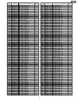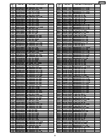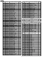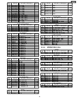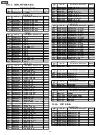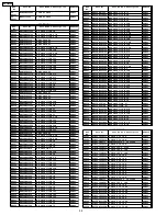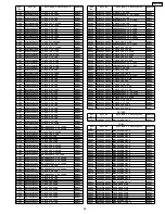
BEFORE REPLACING PARTS, READ THE FOLLOWING:
12.1. REPLACEMENT NOTES
12.1.1. General Notes
1. Use only original replacement parts:
To maintain original function and reliability of repaired units,
use only original replacement parts which are listed with
their part numbers in the parts list.
2. IMPORTANT SAFETY NOTICE
Components identified by the sign
have special
characteristics important for safety. When replacing any of
these components, use only the specified parts.
3. SPECIAL NOTE
All integrated circuits and many other semiconductor
devices are electrostatically sensitive and therefore require
the special handling techniques described under the
"ELECTROSTATICALLY
SENSITIVE
(ES)
DEVICES"
section of this service manual.
4. Parts with no Ref. No. in "EXPLODED VIEWS" are not
supplied. And some Ref. No. will be skipped. Be sure to
make your orders of replacement parts according to the
parts list.
“<R>” in Remarks column indicates recommended parts.
“<M>” in Remarks column
indicates needed in the
periodical maintenance.
5. Parts different in shape or size may be used. However, only
interchangeable
parts
will
be
supplied
as
service
replacement parts.
6. Definition of Parts supplier:
a. Parts with mark "PSEC" in the Remarks column are
supplied from PSEC.
b. Parts with mark "PSECI" in the Remarks column are
supplied from PSECI.
c.
Parts with mark "SPC" in the Remarks column are
supplied from Spare Parts Center of Panasonic AVC
Company.
d. Parts without mark in the Remarks column are supplied
from PASC-NPC.
7. Item numbers with capital letter E (Example: E10, E20,...) in
the Ref. No. column are shown in the exploded views.
8. Parts whose Ref. Nos. are the same are interchangeable as
replacement parts. Any of these parts may be ordered and
used as a replacement part.
12.1.2. Mechanical Replacement Notes
1. Section No. of parts shown in Exploded Views are indicated
in the Remarks column.
2. The Mechanical Chassis Sub Ass’y (Ref. No. 4) consists of
all the mechanical parts except the Cylinder Unit (Ref. No.
1), and the Cassette Up Ass’y (Ref. No. 51) and Cleaner
Arm Unit (Ref. No.3).
After replacing the Mechanical Chassis Sub Ass’y, be sure
to perform “TAPE INTERCHANGEABILITY ADJUSTMENT”
in Service Manual for R4-Mechanism - Chassis - for - PV-
Model (Order No. MKE0401000C1).
3. The
Infrared
Remote
Control
Unit
(Ref.
No.
123)
replacement part is available as a complete assembly unit
only. Do not try to disassemble the Infrared Remote Control
Unit. However, the battery cover is available separately as
a replacement part.
4. When replacing the DVD Frame (Ref. No. 317), be sure to
place the Rating Label (Ref. No. 318) on it.
5. When replacing the DVD Mechanism Unit (Ref. No. 242) or
the DVD Frame (Ref. No. 317), be sure to place the Cabinet
Label (Ref. No. 253) on it.
12.1.3. Electrical Replacement Notes
1. Unless otherwise specified;
All resistors are in
Ω
, K = 1,000
Ω
, M = 1,000 k
Ω
.
2. Abbreviation
RTL:
Retention Time Limited
This indicates that the retention time is
limited for this item. After the
discontinuation of this item in
production, it will no longer be
available.
NR:
Non Repairable Board Ass´y
MGF CHIP:
Metal Glaze Film Chip
C CHIP:
Ceramic Chip
COMPLX CMP:
Complex Component
W FLMPRF:
Wirewound Flameproof
C.B.A.:
Circuit Board Assembly
P.C.B.:
Printed Circuit Board
E.S.D.:
Electrostatically Sensitive Devices
3. When replacing 0
Ω
resistor, a wire can be substituted for
it.
4. Since the UHF/VHF TUNER/TV DEMODULATOR UNIT
(Ref. No. 743) has already been pre-adjusted at the factory,
do
not
try
to
adjust
the
UHF/VHF
TUNER/TV
DEMODULATOR
UNIT.
The
UHF/VHF
TUNER/TV
DEMODULATOR UNIT replacement part is available as a
complete assembly unit only.
5. EEP ROM IC (IC6004) replacement note:
There are 2 types of EEPROM IC (IC6004) used on the
Main C.B.A. (DIP TYPE and SOP TYPE). However, these
are same reliability, please refer to "MAIN C.B.A." in
CIRCUIT BOARD LAYOUT.
12 REPLACEMENT PARTS LISTS
85
AG-520VDH
Summary of Contents for AG520VDH - COMB. DVD/VCR/TV
Page 7: ...4 ABOUT LEAD FREE SOLDER PbF 7 AG 520VDH ...
Page 9: ...Fig 1 6 9 AG 520VDH ...
Page 16: ...5 1 14 WIRE AND LEAD POSITION DIAGRAM Fig 12 16 AG 520VDH ...
Page 18: ...5 2 MAINTENANCE CHART 18 AG 520VDH ...
Page 20: ...Fig D2 20 AG 520VDH ...
Page 21: ...Fig D3 21 AG 520VDH ...
Page 22: ...Fig D4 22 AG 520VDH ...
Page 35: ...7 4 TEST POINTS AND CONTROL LOCATION 35 AG 520VDH ...
Page 36: ...36 AG 520VDH ...
Page 60: ...AG 520VDH 60 ...
Page 78: ...AG 520VDH 78 ...
Page 79: ...11 EXPLODED VIEWS 11 1 MECHANISM SECTION AG 520VDH 79 ...
Page 80: ...11 2 DVD SECTION AG 520VDH 80 ...
Page 81: ...11 3 CHASSIS FRAME SECTION 1 AG 520VDH 81 ...
Page 82: ...11 4 CHASSIS FRAME SECTION 2 AG 520VDH 82 ...
Page 83: ...11 5 CHASSIS FRAME SECTION 3 AG 520VDH 83 ...
Page 84: ...11 6 PACKING PARTS AND ACCESORIES SECTION AG 520VDH 84 ...


